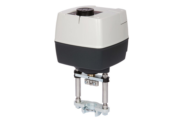
Danfoss Motorized Control Valves (MCV) for district heating and cooling, HVAC and central heating systems ensure stable and accurate control of water, glycol mixtures and steam. This in turn improves temperature control and reliability while increasing the energy efficiency of the system. All of which adds up to enhanced comfort for the end-user. The MCV range comprises both regular and pressure-relieved control valves designed to operate in the most demanding applications.
Danfoss offers a comprehensive range of control valves and actuators for virtually every application: central and decentralized heating systems, domestic hot-water systems, district heating and steam.
For maximum versatility, our control valves and actuators come in different sizes, materials and connection options. They also offer a range of different functions and features to suit each specific application. With a global reputation for quality and reliability, our latest solutions are available at different price points to suit the budgetary needs of every project.
Years of customer insights and product development for district heating, HVAC and central heating applications have enabled us to create a flawless product that perfectly complies with all current requirements and future trends. Here are some of the highlights:
- Excellent control performance
The control capabilities of the MCV range are based on different characteristics, including split characteristics for DHW applications using heat exchangers, as well as linear and logarithmic characteristics. This means that even the most difficult control requirements in district heating can be met, while still providing instantaneous hot water. For DHW systems, the low slope of the split characteristic in this part of the stroke ensures stable control of the valve in the critical area near the closing position. On the other hand, the steeper part of the curve (large flow) enables fast and stable control. - Proven lifetime cost effectiveness
Thanks to easy selection, installation, commissioning and maintenance, Danfoss MCVs simply cost you less time, money and effort. - Easy handling and installation
Danfoss MCVs are easy to handle, easy to operate and easy to understand. Quick connection to actuator and valve is enabled by a threaded coupling, which also allows for rotation after mounting. External LED visualization and signaling save time and effort during installation and commissioning of MCVs. - Increased reliability and operational safety
All new products feature built-in thermic and overload protection of the electromotor. This radically reduces the risk of operational failure in either the valve or the system as a whole.
Features and benefits
Easy selection, installation, commissioning and maintenance mean less time, money and effort
Excellent control performance, even in the most demanding systems
Increased reliability and operational safety due to built-in thermic and overload protection of the electromotor.
Product range
-
if (isSmallPicture) {


 Globe valves
Globe valves ensure stable and accurate control of water. The precise temperature control brings increased comfort and energy savings.
-
if (isSmallPicture) {


 Actuators for globe valves
Actuators provide risk reduction through improved overload protection, which ensures a trouble free operation of the actuator inside the system.
-
if (isSmallPicture) {


 Rotary valves
Rotary valves are primarily designed for regulation of flow and temperature in heating systems where a certain leakage can be accepted and where a defined control characteristic is not required.
-
if (isSmallPicture) {


 On - off motorized zone valves
In a range of on - off motorized zone valves Danfoss offers AMZ 112/113 actuators. They provide an user-friendly, reliable, easy to install and commission product, which fit to every application and increases its flexibility. AMZ is designed to be used in HVAC or CH applications.
Documents
| Type | Name | Language | Valid for | Updated | Download | File type |
|---|---|---|---|---|---|---|
| Brochure | Let motorized intelligence solve your application challenges | Polish | Poland | 09 Nov, 2023 | 2.8 MB | |
| Brochure | Let motorized intelligence solve your application challenges | Finnish | Multiple | 05 Jul, 2023 | 6.3 MB | |
| Brochure | Let motorized intelligence solve your application challenges | Bulgarian | Multiple | 31 Aug, 2015 | 6.2 MB | |
| Brochure | Let motorized intelligence solve your application challenges | Hungarian | Multiple | 25 Jun, 2015 | 1.6 MB | |
| Brochure | Let motorized intelligence solve your application challenges | Italian | Multiple | 04 Nov, 2015 | 6.3 MB | |
| Brochure | Let motorized intelligence solve your application challenges | Slovak | Multiple | 06 Jul, 2015 | 1.7 MB | |
| Brochure | Let motorized intelligence solve your application challenges | Chinese (CN) | Multiple | 18 May, 2015 | 2.0 MB | |
| Brochure | Let motorized intelligence solve your application challenges | Ukrainian | Multiple | 20 Oct, 2015 | 6.2 MB | |
| Brochure | Let motorized intelligence solve your application challenges | Croatian | Multiple | 31 Aug, 2015 | 6.2 MB | |
| Brochure | Let motorized intelligence solve your application challenges | Dutch, Flemish | Multiple | 28 Aug, 2023 | 3.5 MB | |
| Brochure | Let motorized intelligence solve your application challenges | Danish | Multiple | 09 Oct, 2015 | 6.2 MB | |
| Brochure | Let motorized intelligence solve your application challenges | Romanian, Moldavian, Moldovan | Multiple | 20 May, 2015 | 2.1 MB | |
| Brochure | Let motorized intelligence solve your application challenges | Swedish | Multiple | 19 Nov, 2015 | 6.2 MB | |
| Brochure | Let motorized intelligence solve your application challenges | German | Multiple | 08 Jun, 2015 | 6.8 MB | |
| Brochure | Let motorized intelligence solve your application challenges | Lithuanian | Multiple | 11 Nov, 2015 | 3.2 MB | |
| Brochure | Let motorized intelligence solve your application challenges | French | Multiple | 08 Sep, 2015 | 6.3 MB | |
| Brochure | Let motorized intelligence solve your application challenges | Spanish, Castilian | Multiple | 03 Sep, 2015 | 6.2 MB | |
| Brochure | Let motorized intelligence solve your application challenges | Slovenian | Multiple | 01 Sep, 2015 | 1.7 MB | |
| Brochure | Let motorized intelligence solve your application challenges | Czech | Multiple | 07 Aug, 2015 | 1.7 MB | |
| Brochure | Let motorized intelligence solve your application challenges | Serbian (RS) | Multiple | 31 Aug, 2015 | 1.7 MB | |
| Brochure | Motorized Control Valves for district heating & cooling, heating and HVAC systems | English | Multiple | 03 Jul, 2023 | 2.1 MB |
Tools and apps

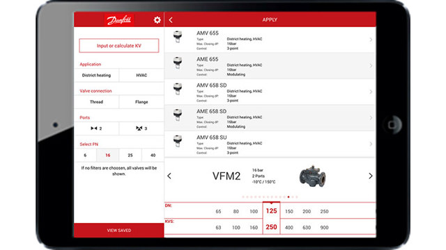
Danfoss Heat Selector
The Danfoss Heat Selector is a best-in-class online selection tool that optimizes planning process for heating application experts.
Application guide
FAQ
Case stories
-
if (isSmallPicture) {


 Ventilation is more energy-efficient in this Illinois factory
USA: The Danfoss Loves Park factory upgraded existing ventilation with the Danfoss Novenco EC+ concept, achieving a 59.8% reduction in emissions compared to the previous system.
-
if (isSmallPicture) {


 Danfoss partners with the city of Banja Luka to decarbonize district energy
The Challenge: Renovate 34 of the city’s largest heating substations
The Solution: Danfoss Leanheat® Monitor enables full substation digitalization
The Results: reduced heat consumption by 10% -
if (isSmallPicture) {


 Wind tunnel achieves 99.5% uptime with Danfoss DrivePro®
Belgium: Thanks to Danfoss DrivePro® services, LuxFly has achieved 99,5% uptime in Europe’s largest vertical wind tunnel that is used for skydiving.
-
if (isSmallPicture) {


 Successful transition from oil boilers to a local heating network in Eurasburg
In the Wittelsbacher Land near Augsburg the local network in Eurasburg supplies heat to 80 buildings using a wood chip heating system. Danfoss’ substations ensure efficient heating in all building types, and its modern SCADA solution enables remote system monitoring and management.
-
if (isSmallPicture) {


 How did this smart factory reach carbon-neutral?
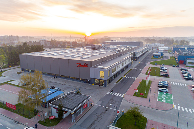
POLAND: The new Danfoss production hall in Grodzisk Mazowiecki has reached carbon-neutrality, thanks to full electrification, energy-saving solutions such as Danfoss drives, and energy from renewable sources.
-
if (isSmallPicture) {


 Retrofitting Keppel Bay Tower for a Zero Energy future
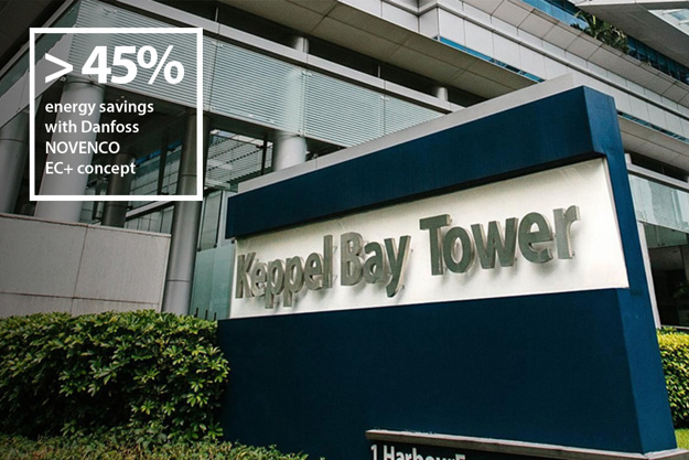
SINGAPORE: With Danfoss EC+ concept for HVAC systems, Keppel Bay Tower uses 45% less energy and has achieved Green Mark Platinum Zero Energy building status.
Videos

Unlock the grid to its full potential
We can help utilities to optimize their supply of district heating to cities with a positive impact on decarbonization and reduced energy consumption. It's time to unlock the grid's full potential for ultimate cost-effectiveness, energy-efficiency and a resilient path to a greener future.

