Features and functionalities of Danfoss ASV-PV
A series of 5 animations describing the challenges, backgrounds and solutions for hydronic balancing of two-pipe heating systems in multi-family buildings.
Documents
Software
Danfoss SET 365 software
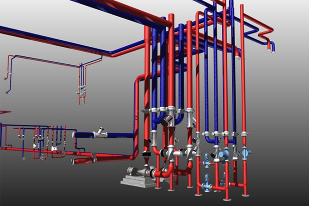
Our advanced Danfoss SET 365 3D design software will help you to design and calculate HVAC systems with Danfoss products. A 1-year subscription is FREE available for students, designers and other interested professionals.
Tools and apps

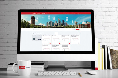
Danfoss Heat Selector is the best-in-class online selection tool that optimizes the planning process for heating application experts.

The Installer App allows you to easily verify the flow in different valves. In the Quick tools section, choose the Hydronic balancing tool. Then select the valve and the desired dimension and get the answer immediately.
3D models and drawings

BIM library for MEP designs
Get your 3D BIM objects and start design dynamic HVAC solutions.
Read more and Download
Case stories
Videos

Tender texts
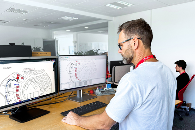
We offer expert hydronic HVAC design and consultancy services at Danfoss' Design Support Center.
Read more