Integrated vibration analysis
Danfoss drives offer unique integrated condition-based monitoring (CBM) functionality. For installed machines currently with no access to condition monitoring data, these drives provide a convenient way to implement monitoring and begin collecting performance data.
Explore more opportunities with condition-based monitoring(CBM)

VFDs act as intelligent sensors for condition monitoring in automated systems. Explore features of intelligent drives and various maintenance strategies.
Monitoring motor performance using condition-based monitoring provides a simple and cost-effective way to obtain machine data for smart maintenance decisions.

Predictive maintenance has emerged as a powerful tool to optimize equipment performance, increase uptime, and reduce maintenance costs.

Remote monitoring empowers users to access real-time data, react early to avoid interruptions, optimize performance, and make informed decisions.

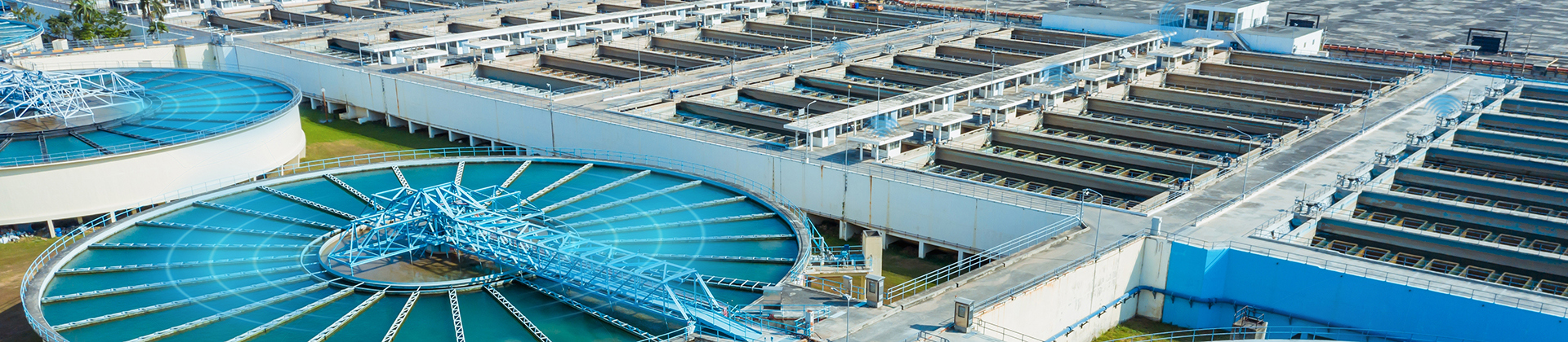
Clogged pumps work less efficiently and use more energy to do their job than clean pumps. If unattended, eventually a clogged pump will grind to a halt, causing unplanned downtime.

Avoid costly pump damage with VFD condition monitoring. Detect cavitation early and protect performance with smart, predictive insights.

Protect motors and extend uptime with sine-wave filter monitoring in Danfoss VLT® drives. No external sensors needed—get early detection and lasting protection.
Highlighted products
Danfoss products using condition-based monitoring
VLT® AQUA Drive FC 202 controls all types of pumps and comes equipped with a cascade controller.
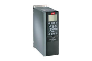
FC 103 is dedicated to controlling compressors, pumps and fans for significant energy savings in refrigeration plants.
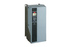
This tough and savvy FC102 drive enhances pump and fan applications in building management systems, and runs outdoors in most climates.
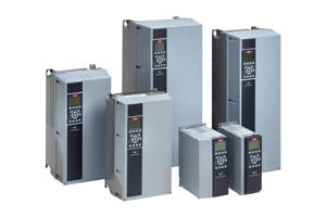
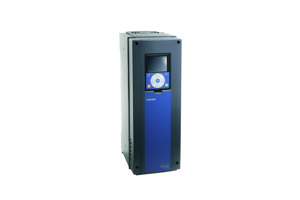
The VLT® AutomationDrive FC 301 / FC 302 is designed for variable speed control of all asynchronous motors and permanent magnet motors. It comes in a standard version (FC 301) and an advanced high dynamic version (FC 302) with additional functionalities.
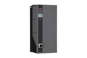
Designed for a broad range of demanding applications, focusing on higher power sizes and system drives.
Drive modules and enclosed drives that are easily integrated into all major control systems.
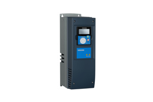
Dedicated functionality that improves flow control and saves energy in industrial pump and fan applications.
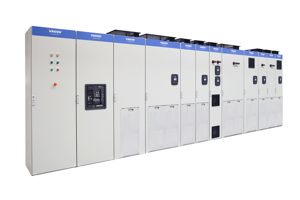
Configured and assembled to meet your needs whether you need to control one or several motors.
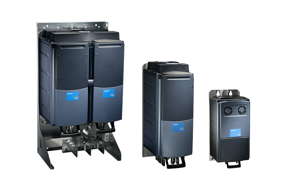
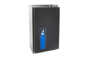
Brings the benefits of liquid-cooling into common DC bus systems in demanding situations. Active Front-end (NXA), Non-regenerative Front-end (NXN), Brake Chopper (NXB) and Inverter (NXI) configurations are available.
Danfoss first innovations
CBM has emerged from a history of Danfoss firsts in innovation. Danfoss drives differentiate from others in the market with intelligent functions embedded in the drive, to reduce the external components required.
Case stories
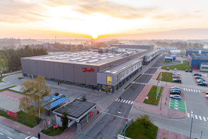
POLAND: The new Danfoss production hall in Grodzisk Mazowiecki has reached carbon-neutrality, thanks to full electrification, energy-saving solutions such as Danfoss drives, and energy from renewable sources.
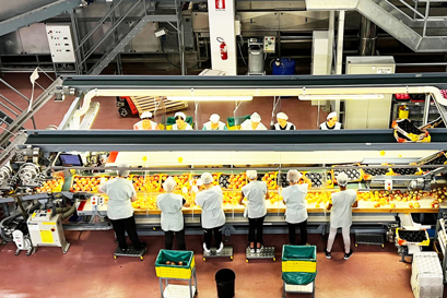
ITALY: At Rivoira Group, VLT® drives with built-in condition-based monitoring help preserve fruit perfectly by ensuring utterly reliable refrigeration.

DENMARK: Universe Science Park saves on both power bill and emissions for its wind tunnel attraction “Beat the Storm”, with the intelligent VLT® HVAC drive.
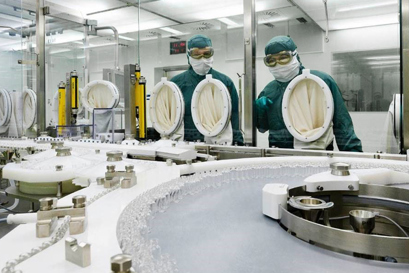
DENMARK: A leading global pharmaceutical company was determined to find an intelligent HVAC solution to prevent downtime with real-time system monitoring and customizable instant alarms. Plus, the solution needed to fit within the organization’s ambitious digitalization strategy. The solution: Danfoss VLT® HVAC Drive FC 102 with integrated condition-based monitoring.

NETHERLANDS: HEINEKEN understands that to meet demand, its production line must always be up to the task – with all assets expected to deliver a consistently reliable and excellent performance. At Den Bosch brewery, the tough working environment posed several challenges. The solution was an upgrade using drives with integrated condition-based monitoring.