
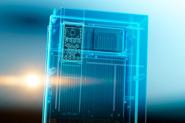
Drives are more than simple power processors
With the ability to act as sensors and sensor hubs, to process, store and analyze data, along with connectivity capabilities, drives are vital elements in modern automation systems and building management systems (BMS). Integrated condition-based monitoring functionality enables new ways of performing maintenance, such as condition-based maintenance.
Integrated intelligence
What is an intelligent drive?
In the Industry 4.0 network, the drive plays an important role and is characterized by some enabling features:
- Secure connectivity: The drive can connect to other elements in a secure manner. Other elements in the network may include drives, PLCs, sensors, and a cloud.
- The drive acts as a sensor: The drive uses motor current and voltage signature analysis to sense the motor and application performance.
- The drive acts as a sensor hub: The drive acquires data from external sensors related to the process which is controlled by the drive.
- The drive acts as a controller: The drive can replace the PLC wherever application constraints allow.
- Bring your own device concept: Wireless connectivity to smart devices (smartphone, tablet).
Information from the drive can be identified as follows:
- Instantaneous signals: Signals which are directly measured by the drive using built-in sensors. Data such as motor current, voltage, drive temperature, and their derivative, which is power as a multiplication of current and voltage, or motor torque. Moreover, the drive can be used as a hub for connecting external sensors which provide instantaneous signals.
- Processed signals: Signals which are derived from the instantaneous signals. For example, statistical distribution (maximum, minimum, mean and standard deviation values), frequency domain analysis or mission profile indicators.
- Analytics signals: Signals which provide indications of the condition of the drive, motor and application. The signals are used to trigger maintenance or lead to system design improvements.
Motor current signature analysis techniques enable the drive to monitor the condition of the motor and application. The technique allows to potentially eliminate physical sensors or extract early fault signatures which might not have been possible to detect. For example, using the technique makes it possible to detect cavitation and winding faults in advance or mechanical load eccentricity.
The concept of the drive as a sensor hub entails connecting external sensors to the drive, thus saving the need for a gateway to connect the physical sensor to the data network. Vibration sensors, pressure sensors, and temperature sensors are examples of sensors which can be connected to the drive. The advantage of the concept is not only related to cost, but also enabling the correlation of sensor data with different types of data present in the drive. An obvious example is the correlation of vibration level from an external sensor with the motor speed, as vibration is speed dependent.
CBM in 3 steps
Explore opportunities with CBM
Monitoring motor performance using condition-based monitoring provides a simple and cost-effective way to obtain machine data for smart maintenance decisions.

Predictive maintenance has emerged as a powerful tool to optimize equipment performance, increase uptime, and reduce maintenance costs.

Remote monitoring empowers users to access real-time data, react early to avoid interruptions, optimize performance, and make informed decisions.
Along with stator winding monitoring and load envelope, the CBM functionality integrated into Danfoss drives includes vibration monitoring.

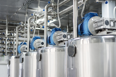
Clogged pumps work less efficiently and use more energy to do their job than clean pumps. If unattended, eventually a clogged pump will grind to a halt, causing unplanned downtime.

Avoid costly pump damage with VFD condition monitoring. Detect cavitation early and protect performance with smart, predictive insights.

Protect motors and extend uptime with sine-wave filter monitoring in Danfoss VLT® drives. No external sensors needed—get early detection and lasting protection.
Maximize performance with 24/7 condition monitoring

In air flow and indoor air quality-related applications, condition monitoring functionality improves system uptime and competitiveness by preventing issues before they occur.
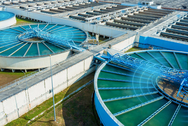
In water and wastewater applications, activating a condition monitoring system integrated into your VSDs optimizes the overall performance. Edge computing means there is no need to connect to the cloud.

Refrigeration systems preserve apple quality using VSDs with integrated condition monitoring and DrivePro Remote Monitoring service
ITALY: At Rivoira Group, VLT® drives with built-in condition-based monitoring help preserve fruit perfectly by ensuring utterly reliable refrigeration.
Read the case study
Driving maximum uptime in aseptic pharmaceutical production
DENMARK: A leading global pharmaceutical company was determined to find an intelligent HVAC solution to prevent downtime with real-time system monitoring and customizable instant alarms. Plus, the solution needed to fit within the organization’s ambitious digitalization strategy. The solution: Danfoss VLT® HVAC Drive FC 102 with integrated condition-based monitoring.
Read the case study

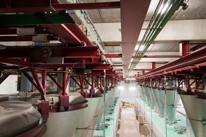
Brewing up real change at HEINEKEN
NETHERLANDS: HEINEKEN understands that to meet demand, its production line must always be up to the task – with all assets expected to deliver a consistently reliable and excellent performance. At Den Bosch brewery, the tough working environment posed several challenges. The solution was an upgrade using drives with integrated condition-based monitoring.
Read the case study

Danfoss first innovations
CBM has emerged from a history of Danfoss firsts in innovation. Danfoss drives differentiate from others in the market with intelligent functions embedded in the drive, to reduce the external components required.
More about Danfoss drives