Built-in intelligence to keep your system running
Intelligence embedded in the VLT® AQUA Drive FC 202 automatically defines baseline parameters for water and wastewater applications, at all speeds and real-life operating cycles. In the event an issue is detected, Digital cascade control Hot Swap technology combined with back-up master functionality ensures reliable, stable and easy operation to help you stay up and running. In addition to the features provide by the VLT AQUA Drive, Danfoss offers DrivePro®-tection which provides up to a 6 year on-site warranty to insure continued operation of your drive.
Maximum energy efficiency for water, wastewater, and variable torque applications
The VLT® AQUA Drive FC 202 is designed to provide the highest level of performance of AC-motor-driven applications. Featuring a wide range of powerful standard features, which can be expanded with performance-improving options, the drive is equally suited to both new and retrofit projects.
The VLT® AQUA Drive can realistically offer first-year cost savings of between 10–30% compared to traditional drive solutions. Long equipment life, and low energy consumption and maintenance costs come together to provide the lowest cost of ownership. The quick and user-friendly setup reduces installation time ensuring a fast route to maximum energy efficiency and motor control.
Water and wastewater applications
The considerable daily load variation in water or wastewater treatment plants makes it economically feasible to introduce motor control on rotating equipment such as pumps and blowers.
Industrial VT applications
The VLT® AQUA Drive the perfect match for Industrial VT applications including fans, pumps, blowers, and compressors. It is a direct replacement for the FC 322. Available in a wide range of industrial enclosures from protected chassis to IP 66 (NEMA 4 X Indoor).
Supply voltages and power range
- 1 x 200-240 V...1.1-22 kW
- 1 x 380-480 V...7.5-37 kW
- 3 x 200-240 V...0.25-150 kW
- 3 x 380-480 V...0.37 kW – 1 MW
- 3 x 525-600 V...0.75-90 kW
- 3 x 525-690 V...1.1 kW – 1.4 MW
Low harmonic drive
- 3 x 380-480 V...132-450 kW
12-pulse drive
- 3 x 380-500...250-1000 kW
- 3 x 525-690...250-1400 kW
Simulate the savings— proof is in the details

Download the VLT® AQUA Drive Simulator and see how installing Danfoss drives will improve your efficiency.
Features and benefits
-
Assets are protected thanks to specially designed software that prevents, for example, water hammering
-
Energy efficiency is maximized as a result of the drives control algorithms and design which focus on reducing heat loss
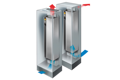
-
High energy savings related to air conditioning are ensured due to the unique back-channel-cooling concept that transfers 90% of heat away from the room
-
Electromagnetic interference and harmonic distortion are reduced thanks to the built-in, scalable RFI filter and integrated DC link chokes
-
Perfect system integration and adaptation to the application are possible due to freely programmable warnings and alerts
-
3–8% energy savings are achieved as a result of Automatic Energy Optimization

Safeguard your investment
Register your drive and see if you qualify for a 12 month warranty extension.
Offer only available in the United States and Canada.
Register Your Drive
Get more information

VLT® AQUA Drive brochure
View the PDF of the North American VLT® AQUA Drive brochure for up to date information on the FC 202 and the water/wastewater industry.
View the brochure
VLT® AQUA Drive literature
Documents
| Type | Name | Language | Valid for | Updated | Download | File type |
|---|---|---|---|---|---|---|
| Brochure | 9 Tips towards energy efficiency | English | Multiple | 09 Jan, 2023 | 79.2 MB | |
| Brochure | 9 Tips towards energy efficiency - English US | English | United States | 14 Jun, 2023 | 77.8 MB | |
| Case story | Acciona | English | Multiple | 06 Feb, 2023 | 3.6 MB | |
| Operating guide | Add-On Instr VLT EtherNet-IP MCA 121 | English | Multiple | 14 Feb, 2017 | 1.1 MB | |
| Case story | AEL | English | Multiple | 20 Mar, 2023 | 2.1 MB | |
| Case story | Affinity Water | English | Multiple | 22 Sep, 2022 | 3.3 MB | |
| Case story | Amager Power Plant | English | Multiple | 17 Jul, 2023 | 2.1 MB | |
| Case story | Ashburton Irrigation NZ | English | Multiple | 20 Jul, 2023 | 1.4 MB | |
| Case story | Bignardi Effluent Pumping | English | Multiple | 20 Jul, 2023 | 789.1 KB | |
| Case story | BMG South Africa | English | Multiple | 20 Mar, 2023 | 2.4 MB | |
| Case story | Cafoeidian Desalination | English | Multiple | 20 Jul, 2023 | 1.7 MB | |
| Operating guide | Cascade Controller Options MCO 101-102 | English | Multiple | 14 Aug, 2020 | 2.1 MB | |
| Case story | Catagena WWTP Colombia | English | Multiple | 20 Jul, 2023 | 1.9 MB | |
| Case story | CPH Energy District Cooling - 2014 | English | Multiple | 06 Feb, 2023 | 1.6 MB | |
| Case story | CPH Energy District Cooling - 2018 | English | Multiple | 06 Feb, 2023 | 1.6 MB | |
| Brochure | Danfoss Drives Fieldbus Solutions | English | Multiple | 11 Nov, 2021 | 7.7 MB | |
| Brochure | DrivePro® Services Overview | English | Multiple | 03 Feb, 2025 | 26.8 MB | |
| Brochure | DrivePro® Services Overview - US English | English | United States | 03 Feb, 2025 | 26.6 MB | |
| Fact sheet | Extended functionality and real LHD for high-performance operation | English | Multiple | 18 Jul, 2023 | 1.4 MB | |
| Fact sheet | Fact Sheet - VLT® Wireless Communication Panel LCP 103 Wireless connectivity to your drive | English | Multiple | 07 Mar, 2023 | 1.4 MB | |
| Fact sheet | Factsheet - VLT® AQUA Drive deragging feature keeps your wastewater pumps clean | English | Multiple | 24 Mar, 2023 | 1.9 MB | |
| Case story | FlexHeat | English | Multiple | 20 Mar, 2023 | 2.7 MB | |
| Brochure | Harmonics in water & wastewater | English | Multiple | 09 Jun, 2023 | 17.1 MB | |
| Brochure | Harmonics in water & wastewater | US English | English | United States | 15 Jun, 2023 | 16.9 MB | |
| Case story | Heat Recovery DN | English | Multiple | 22 Aug, 2022 | 4.5 MB | |
| Case story | Hjoerring Multi Biofuel | English | Multiple | 03 May, 2023 | 4.3 MB | |
| Case story | Hofor District Cooloing | English | Multiple | 21 Mar, 2023 | 4.3 MB | |
| White paper | Impact of IEC 61800-5-1:2022 on variable frequency drives (VFD) | English | Multiple | 20 Mar, 2026 | 4.6 MB | |
| Fact sheet | IP 66/Type 4x enclosed VLT® drives up to 90 kW | English | Multiple | 11 Aug, 2023 | 888.9 KB | |
| Case story | Jersey Water | English | Multiple | 22 Mar, 2023 | 6.9 MB | |
| Case story | Jersey Water - US English | English | United States | 22 Mar, 2023 | 7.4 MB | |
| Case story | Jurex Romania Irrigation | English | Multiple | 16 Sep, 2022 | 1.3 MB | |
| Case story | Kalundborg Bioenergy | English | Multiple | 22 Mar, 2023 | 3.1 MB | |
| Case story | Koyambedu WWTP - Short case | English | Multiple | 27 Mar, 2023 | 801.4 KB | |
| Case story | Lisbjerg Incineration | English | Multiple | 07 Jun, 2023 | 3.2 MB | |
| White paper | Marselisborg WWTP | English | Multiple | 18 Oct, 2022 | 10.4 MB | |
| Case story | Marselisborg WWTP | English | Multiple | 02 Sep, 2022 | 7.0 MB | |
| Application guide | Marselisborg WWTP - English | English | Multiple | 14 Oct, 2022 | 1.8 MB | |
| Case story | Marselisborg WWTP 2022 - Full case | English | Multiple | 20 Oct, 2022 | 14.8 MB | |
| Case story | Mayer WWTP | English | Multiple | 03 May, 2023 | 3.4 MB | |
| Case story | Midwest Deep Well | English | Multiple | 20 Jul, 2023 | 2.3 MB | |
| Brochure | Mining and mineral processing | English | Multiple | 11 Nov, 2021 | 44.2 MB | |
| Brochure | Motor technologies | English | Multiple | 18 Nov, 2021 | 7.5 MB | |
| Fact sheet | Mount your drive where you want to...not where you have to | English | United States | 13 Jun, 2023 | 2.7 MB | |
| Fact sheet | Mount your drive where you want to...not where you have to | English | Multiple | 13 Jun, 2023 | 2.9 MB | |
| Application guide | MultiMaster Cascade Control AG | English | Multiple | 21 Feb, 2025 | 4.6 MB | |
| Case story | NORDEN Shipping | English | Multiple | 20 Mar, 2023 | 2.0 MB | |
| Case story | Nordlaks Norway | English | Multiple | 23 Mar, 2023 | 2.7 MB | |
| Case story | Northumbrian Water | English | Multiple | 20 Jul, 2023 | 1.0 MB | |
| Case story | Oestersund Stadium SE | English | Multiple | 20 Jul, 2023 | 429.0 KB | |
| Case story | Orientarium - Short case | English | Multiple | 11 Nov, 2022 | 7.6 MB | |
| Fact sheet | Panel through mount accessory | English | Multiple | 08 Aug, 2023 | 1.1 MB | |
| Case story | Putrajaya | English | Multiple | 15 Sep, 2022 | 1.7 MB | |
| Case story | Racetrack Imola | English | Multiple | 22 Sep, 2022 | 1.3 MB | |
| Fact sheet | Reduce energy costs with intelligent heat management | English | United States | 19 Jul, 2023 | 1.2 MB | |
| Fact sheet | Remote LCP holder - English | English | Multiple | 09 Feb, 2023 | 630.1 KB | |
| Operating guide | Safe Torque Off | English | Multiple | 13 Dec, 2022 | 501.0 KB | |
| Case story | Silkeborg Solvarmeanlaeg | English | Multiple | 20 Oct, 2022 | 4.2 MB | |
| Application guide | Submersible Pump Appl. for VLT® FC 200 | English | Multiple | 13 Jan, 2010 | 205.5 KB | |
| Brochure | Ten things you need to know about Ecodesign | English | Multiple | 27 Feb, 2023 | 574.9 KB | |
| Case story | TMVW Water Belgium | English | Multiple | 20 Jul, 2023 | 2.1 MB | |
| Case story | Unilever Boilerhouse | English | Multiple | 19 Jul, 2023 | 1.6 MB | |
| Case story | Van Asten | English | Multiple | 22 Mar, 2023 | 19.9 MB | |
| Operating guide | VLT ® Modbus RTU | English | Multiple | 27 Oct, 2011 | 1.5 MB | |
| Fact sheet | VLT AQUA Drive FC 202 | English | Multiple | 31 Mar, 2023 | 938.7 KB | |
| Fact sheet | VLT AQUA Drive FC 202 - US English | English | United States | 12 Jul, 2024 | 923.6 KB | |
| Brochure | VLT AQUA Drive FC 202 Selection Guide | English | Multiple | 25 Mar, 2025 | 35.6 MB | |
| Brochure | VLT AQUA Drive FC 202 Selection Guide - US English | English | United States | 22 May, 2024 | 54.0 MB | |
| Operating guide | VLT AQUA Drive FC202, 100-800kW Op.Guide | English | Multiple | 14 Feb, 2022 | 19.6 MB | |
| White paper | VLT drives with integrated CBM | English | Multiple | 24 Jun, 2024 | 13.3 MB | |
| Application guide | VLT drives with integrated CBM | English | Multiple | 14 May, 2022 | 1.2 MB | |
| Fact sheet | VLT® 12-pulse drive | English | Multiple | 19 Jul, 2023 | 1.5 MB | |
| Design guide | VLT® Advanced Harmonic Filter AHF005-010 | English | Multiple | 28 Jan, 2026 | 7.3 MB | |
| Application guide | VLT® AQUA Drive Closed Loop - Sleep Mode | English | Multiple | 13 Jan, 2010 | 183.0 KB | |
| Operating guide | VLT® AQUA Drive D-Frame 110–400 kW | English | Multiple | 14 Feb, 2022 | 13.0 MB | |
| Brochure | VLT® AQUA Drive FC 200 - Engineering Guide | English | Multiple | 18 Aug, 2023 | 21.7 MB | |
| Design guide | VLT® AQUA Drive FC 202 0.25-90 kW | English | Multiple | 14 Sep, 2020 | 8.8 MB | |
| Operating guide | VLT® AQUA Drive FC 202 0.25-90 kW | English | Multiple | 14 Jan, 2022 | 4.1 MB | |
| Operating guide | VLT® AQUA Drive FC 202 110-1400 kW | English | Multiple | 14 Dec, 2021 | 6.3 MB | |
| Design guide | VLT® AQUA Drive FC 202 355-1400 kW | English | United States | 14 Nov, 2017 | 8.0 MB | |
| Design guide | VLT® AQUA Drive FC 202 355-1400 kW | English | Multiple | 14 Nov, 2017 | 12.2 MB | |
| Operating guide | VLT® AQUA Drive FC 202 355–800kW E1h–E4h | English | Multiple | 14 Mar, 2022 | 19.0 MB | |
| Operating guide | VLT® AQUA Drive FC 202 Low Harmonic D | English | Multiple | 14 Feb, 2022 | 22.1 MB | |
| Operating guide | VLT® AQUA Drive FC 202 Low Harmonic D | English | United States | 14 Feb, 2022 | 17.7 MB | |
| Design guide | VLT® AQUA Drive FC 202, 110–800 kW, D,E | English | Multiple | 14 Feb, 2022 | 14.5 MB | |
| Design guide | VLT® AQUA Drive FC 202, 110–800 kW, D,E | English | United States | 14 Feb, 2022 | 14.9 MB | |
| Operating guide | VLT® AQUA Drive FC 202, 12 Pulse | English | Multiple | 14 Jan, 2022 | 5.5 MB | |
| Application guide | VLT® AQUA Drive Master-Follower Operat. | English | Multiple | 13 Jan, 2010 | 293.5 KB | |
| Operating guide | VLT® AQUA FC 202 110-1400 kW | English | United States | 14 Jan, 2022 | 17.1 MB | |
| Operating guide | VLT® AQUA FC 202 12-Pulse High Power | English | United States | 14 Jan, 2022 | 4.5 MB | |
| Operating guide | VLT® AQUA Low Harmonic Drive Manual 1.84 | English | Multiple | 18 Dec, 2011 | 9.7 MB | |
| Operating guide | VLT® AQUA Low Harmonic Drive SW 1.33 | English | United States | 15 Oct, 2009 | 7.3 MB | |
| Design guide | VLT® Brake Resistor MCE 101 | English | Multiple | 07 May, 2014 | 8.5 MB | |
| Fact sheet | VLT® DeviceNet MCA 104 | English | Multiple | 09 Aug, 2023 | 985.8 KB | |
| Operating guide | VLT® DeviceNet MCA 104 | English | Multiple | 26 Mar, 2015 | 3.5 MB | |
| Fact sheet | VLT® drive with enclosure size D - English | English | Multiple | 07 Feb, 2023 | 474.0 KB | |
| Fact sheet | VLT® drive with enclosure size E - English | English | Multiple | 24 Jan, 2023 | 551.8 KB | |
| Fact sheet | VLT® drive with enclosure size E - US English | English | United States | 25 Jan, 2023 | 531.1 KB | |
| Application guide | VLT® Drives Motor overload protection | English | Multiple | 18 Aug, 2008 | 212.6 KB | |
| Fact sheet | VLT® EtherNet/IP MCA 121 | English | Multiple | 09 Aug, 2023 | 635.4 KB | |
| Application guide | VLT® FC 200 Motor cont. run at low speed | English | Multiple | 19 Aug, 2008 | 157.0 KB | |
| Operating guide | VLT® FC Series Option Panel | English | Multiple | 13 Nov, 2012 | 4.3 MB | |
| Design guide | VLT® FC Series Output Filter Design G. | English | Multiple | 21 Feb, 2011 | 4.8 MB | |
| Brochure | VLT® Functional Safety | English | Multiple | 11 Nov, 2021 | 2.7 MB | |
| Fact sheet | VLT® Low Harmonic Drive | English | Multiple | 19 Jul, 2023 | 673.1 KB | |
| Operating guide | VLT® Metasys N2 FC 102 and FC 202 series | English | Multiple | 11 Feb, 2010 | 552.8 KB | |
| Fact sheet | VLT® Modbus TCP MCA 122 | English | Multiple | 09 Aug, 2023 | 818.2 KB | |
| Operating guide | VLT® Modbus TCP MCA 122 | English | Multiple | 01 May, 2013 | 3.4 MB | |
| Fact sheet | VLT® Parallel Drive Modules | English | Multiple | 11 Aug, 2023 | 446.0 KB | |
| Operating guide | VLT® Parallel Drive Modules 250-1200 kW | English | Multiple | 03 Aug, 2017 | 8.5 MB | |
| Design guide | VLT® Parallel Drive Modules, 250–1200 kW | English | Multiple | 14 Aug, 2017 | 16.4 MB | |
| Fact sheet | VLT® PROFINET MCA 120 | English | Multiple | 09 Aug, 2023 | 663.4 KB | |
| Fact sheet | VLT® PTC Thermistor Card MCB 112 | English | Multiple | 09 Aug, 2023 | 693.8 KB | |
| Operating guide | VLT® PTC Thermistor Card MCB 112 | German; English | Multiple | 19 Dec, 2023 | 3.0 MB | |
| Operating guide | VLT® PTC Thermistor Card MCB 112 | English | Multiple | 15 Jul, 2024 | 1.2 MB | |
| Brochure | VLT® Pump Control OEM | English | Multiple | 21 Nov, 2021 | 15.1 MB | |
| Fact sheet | VLT® Real-time Clock MCB 117 | Advanced data logging by time stamping | English | Multiple | 26 Apr, 2023 | 288.1 KB | |
| Case story | Yen So Park WWTP | English | Multiple | 20 Jul, 2023 | 1.9 MB |
Drawings
Frame Ratings by HP
Contact factory for drives larger than 350HP
Additional mechanical drawings including drawings for Drives with options, electrical drawings and E-Plan files are located below this table under the heading 3D models and drawings.
Frame |
Enclosure |
HP Range |
Base drive dimensions (Inches) |
Mechanical drawing # |
|||||||
NEMA 1 |
NEMA 12 |
208V |
460V |
600V |
Height |
Width |
Depth |
T1 |
T2 |
T3 |
|
A2 |
O | 0.5-3 | 0.5-5 | - | 14.6 | 3.5 | 8.1 | 176U8484 | 176U8485 | 176U5288 | |
A3 |
O | 5 | 7.5-10 | 0.5-10 | 5.1 | ||||||
A5 |
O | 0.5-5 | 0.5-10 | 0.5-10 | 16.5 | 9.5 | 7.9 | 176U5289 | 176U5290 | 176U3833 | |
B1 |
O | O | 7.5 - 15 | 15-25 | 18.9 | 9.5 | 10.3 | 176U8471 | 176U8472 | 176U8473 | |
B2 |
O | O | 20 | 30-40 | 25.6 | 176U8474 | 176U8475 | 176U8476 | |||
C1 |
O | O | 25-40 | 50-75 | 26.8 | 12.1 | 12.2 | 176U8477 | 176U8463 | 176U8479 | |
C2 |
O | O | 50-60 | 100-125 | 30.3 | 14.6 | 13.2 | 176U8480 | 176U8481 | 176U8482 | |
D1 |
O | O | - | 150-200 | 150-250 | 45.6 | 16.5 | 14.7 | 176U8435 | ||
D2 |
O | O | 250-350 | 300-350 | 60.6 | ||||||
D1h |
O | O | - | 150-200 | 150-250 | 35.5 | 12.8 | 14.9 | 177R0490 | 174N8666 | |
D2h |
O | O | 250-350 | 300-350 | 43.6 | 16.5 | 176U8480 | ||||
Tier Code Description
- T1 Drive with disconnect or fused disconnect (All frames). T1 drawings are also valid for stand alone drives frame size A5 and larger.
- T2 Drive with bypass or non-bypass panels with contactor motor selection, reactor or dV/dt filter
- T3 Drive with bypass and non-bypass panels with contactor motor selection, reactor or dV/dt filter
To sort drawings in the 3D models and drawings table below, click on the filter icon to the right of the column title "Type" (shown circled at right):
3D models and drawings
| Type | Name | Language | Updated | Download | File type |
|---|---|---|---|---|---|
| Eplan drawing | 130B1102_Eplan | 04 Feb, 2026 | 1.0 MB | .zip | |
| Eplan drawing | 130B1118_EPlan | 04 Feb, 2026 | 203.3 KB | .zip | |
| Eplan drawing | 130B1119_Eplan | 04 Feb, 2026 | 1.1 MB | .zip | |
| Eplan drawing | 130B1137_EPlan | 03 Feb, 2026 | 1.0 MB | .zip | |
| Eplan drawing | 130B1143_Eplan | 04 Feb, 2026 | 1.4 MB | .zip | |
| Eplan drawing | 130B1154_EPlan | 04 Feb, 2026 | 283.9 KB | .zip | |
| Eplan drawing | 130B1164_MCB 113 | 26 Mar, 2026 | 244.4 KB | .zip | |
| Eplan drawing | 130B1172_Eplan | 04 Feb, 2026 | 1.4 MB | .zip | |
| Eplan drawing | 130B1196_Eplan | 04 Feb, 2026 | 816.3 KB | .zip | |
| Eplan drawing | 130B1202_Eplan | 04 Feb, 2026 | 1.0 MB | .zip | |
| Eplan drawing | 130B1218_Eplan | 04 Feb, 2026 | 203.2 KB | .zip | |
| Eplan drawing | 130B1219_Eplan | 04 Feb, 2026 | 1.1 MB | .zip | |
| Eplan drawing | 130B1243-Eplan | 04 Feb, 2026 | 1.4 MB | .zip | |
| Eplan drawing | 130B1254_Eplan | 04 Feb, 2026 | 283.8 KB | .zip | |
| Eplan drawing | 130B1264_MCB 113 Coated | 31 Mar, 2026 | 244.3 KB | .zip | |
| Eplan drawing | 130B1272-Eplan | 04 Feb, 2026 | 1.4 MB | .zip | |
| Eplan drawing | 130B1296_Eplan | 04 Feb, 2026 | 816.2 KB | .zip | |
| Eplan drawing | 131B8932_Eplan | 07 Apr, 2026 | 1.3 MB | .zip | |
| Eplan drawing | 131F1415_Eplan | 04 Feb, 2026 | 1.8 MB | .zip | |
| Eplan drawing | 131F6637_Eplan | 04 Feb, 2026 | 2.0 MB | .zip | |
| Eplan drawing | 131Z7457_Eplan | 04 Feb, 2026 | 1.6 MB | .zip | |
| Eplan drawing | 132X7454_Eplan | 04 Feb, 2026 | 837.6 KB | .zip | |
| Eplan drawing | 134F4192_Eplan | 04 Feb, 2026 | 1.7 MB | .zip | |
| Eplan drawing | 134F7858_Eplan | 07 Apr, 2026 | 1.4 MB | .zip | |
| Eplan drawing | 134X1360_Eplan | 04 Feb, 2026 | 1.8 MB | .zip | |
| Eplan drawing | 135N7267_Eplan | 04 Feb, 2026 | 5.0 MB | .zip | |
| Eplan drawing | 135U8243_Eplan | 14 May, 2026 | 5.4 MB | .zip | |
| Eplan drawing | 135X3625_Eplan | 04 Feb, 2026 | 1.6 MB | .zip | |
| Eplan drawing | 136U2457_Eplan | 04 Feb, 2026 | 813.9 KB | .zip | |
| Eplan drawing | 137N8354_Eplan | 04 Feb, 2026 | 1.6 MB | .zip | |
| Eplan drawing | 137U2626_Eplan | 04 Feb, 2026 | 2.1 MB | .zip | |
| Eplan drawing | 137U7850_Eplan | 04 Feb, 2026 | 1.7 MB | .zip | |
| Eplan drawing | 137X5801_Eplan | 04 Feb, 2026 | 1.9 MB | .zip | |
| Eplan drawing | 137X6109_Eplan | 04 Feb, 2026 | 990.7 KB | .zip | |
| Eplan drawing | 137X7791_Eplan | 10 Mar, 2026 | 5.5 MB | .zip | |
| Eplan drawing | 167F1473_Eplan | 04 Feb, 2026 | 1.3 MB | .zip | |
| Circuit diagram | 174N3178 - Electrical Submittal Drawing | 04 Feb, 2026 | 125.8 KB | ||
| Circuit diagram | 174N3179 - Electrical Submittal Drawing | 05 Feb, 2026 | 124.1 KB | ||
| Dimensional drawing | 175R5955 E1-E2 Mechanical submittal | 20 Feb, 2026 | 137.2 KB | .jpg | |
| Dimensional drawing | 175R5955 E1-E2 Mechanical submittal | 19 Feb, 2026 | 214.2 KB | .jpg | |
| Dimensional drawing | 175R5955 E1-E2 Mechanical submittal | 19 Feb, 2026 | 147.2 KB | .jpg | |
| Dimensional drawing | 175R5955 E1-E2 Mechanical submittal | 19 Feb, 2026 | 2.6 MB | ||
| Dimensional drawing | 176U5289 - Mechanical Submittal Drawing | 19 Feb, 2026 | 112.8 KB | ||
| Dimensional drawing | 176U5289 - Mechanical Submittal Drawing | 20 Feb, 2026 | 875.1 KB | .jpg | |
| Dimensional drawing | 176U8435 - Mechanical Submittal for APU | 19 Feb, 2026 | 369.1 KB | ||
| Dimensional drawing | 176U8435 - Mechanical Submittal for APU | 20 Feb, 2026 | 874.0 KB | .jpg | |
| Dimensional drawing | 176U8435 - Mechanical Submittal for APU | 19 Feb, 2026 | 813.8 KB | .jpg | |
| Dimensional drawing | 176U8435 - Mechanical Submittal for APU | 19 Feb, 2026 | 825.2 KB | .jpg | |
| Dimensional drawing | 176U8435 - Mechanical Submittal for APU | 19 Feb, 2026 | 673.6 KB | .jpg | |
| Dimensional drawing | 176U8435 - Mechanical Submittal for APU | 19 Feb, 2026 | 893.3 KB | .jpg | |
| Dimensional drawing | 176U8471 - Mechanical Submittal Drawing | 19 Feb, 2026 | 115.4 KB | ||
| Dimensional drawing | 176U8471 - Mechanical Submittal Drawing | 19 Feb, 2026 | 912.2 KB | .jpg | |
| Dimensional drawing | 176U8474 - Mechanical Submittal Drawing | 19 Feb, 2026 | 885.3 KB | .jpg | |
| Dimensional drawing | 176U8474 - Mechanical Submittal Drawing | 19 Feb, 2026 | 110.6 KB | ||
| Dimensional drawing | 176U8477 - Mechanical Submittal Drawing | 19 Feb, 2026 | 131.6 KB | ||
| Dimensional drawing | 176U8477 - Mechanical Submittal Drawing | 20 Feb, 2026 | 973.5 KB | .jpg | |
| Dimensional drawing | 176U8480 - Mechanical Submittal Drawing | 19 Feb, 2026 | 135.4 KB | ||
| Dimensional drawing | 176U8480 - Mechanical Submittal Drawing | 19 Feb, 2026 | 129.3 KB | .png | |
| Dimensional drawing | 176U8484 - Mechanical Submittal Drawing | 20 Feb, 2026 | 240.2 KB | ||
| Dimensional drawing | 177R0084 - Mechanical Submittal Drawing | 19 Feb, 2026 | 204.5 KB | ||
| Dimensional drawing | 177R0084 - Mechanical Submittal Drawing | 20 Feb, 2026 | 1.3 MB | .jpg | |
| Dimensional drawing | FC 202 A3 enclosure IP20 A PDF | 17 Feb, 2026 | 609.4 KB | .jpg | |
| Dimensional drawing | FC 202 A3 enclosure IP20 A PDF | 17 Feb, 2026 | 190.3 KB | ||
| Dimensional drawing | FC 202 A3 enclosure IP20 AB PDF | 17 Feb, 2026 | 187.6 KB | ||
| Dimensional drawing | FC 202 A3 enclosure IP20 AB PDF | 17 Feb, 2026 | 597.2 KB | .jpg | |
| Dimensional drawing | FC 202 A3 enclosure IP20 ABC PDF | 20 Feb, 2026 | 196.3 KB | ||
| Dimensional drawing | FC 202 A3 enclosure IP20 ABC PDF | 17 Feb, 2026 | 839.9 KB | .jpg | |
| Dimensional drawing | FC 202 A3 enclosure IP20 AC PDF | 17 Feb, 2026 | 221.3 KB | ||
| Dimensional drawing | FC 202 A3 enclosure IP20 AC PDF | 18 Feb, 2026 | 838.4 KB | .jpg | |
| Dimensional drawing | FC 202 A3 enclosure IP20 B PDF | 18 Feb, 2026 | 572.7 KB | .jpg | |
| Dimensional drawing | FC 202 A3 enclosure IP20 B PDF | 20 Feb, 2026 | 183.9 KB | ||
| Dimensional drawing | FC 202 A3 enclosure IP20 C PDF | 18 Feb, 2026 | 183.3 KB | ||
| Dimensional drawing | FC 202 A3 enclosure IP20 C PDF | 20 Feb, 2026 | 791.1 KB | .jpg | |
| Dimensional drawing | FC 202 A3 enclosure IP20 PDF | 20 Feb, 2026 | 185.9 KB | ||
| Dimensional drawing | FC 202 A3 enclosure IP20 PDF | 17 Feb, 2026 | 566.2 KB | .jpg | |
| Dimensional drawing | FC 202 A3 enclosure IP21 B PDF | 17 Feb, 2026 | 707.3 KB | .jpg | |
| Dimensional drawing | FC 202 A3 enclosure IP21 B PDF | 17 Feb, 2026 | 160.4 KB | ||
| Dimensional drawing | FC 202 A3 enclosure IP21 PDF | 17 Feb, 2026 | 157.5 KB | ||
| Dimensional drawing | FC 202 A3 enclosure IP21 PDF | 20 Feb, 2026 | 683.9 KB | .jpg | |
| Dimensional drawing | FC 202 A4 enclosure IP55-66 PDF | 18 Feb, 2026 | 428.9 KB | ||
| Dimensional drawing | FC 202 A4 enclosure IP55-66 PDF | 17 Feb, 2026 | 330.9 KB | .jpg | |
| Dimensional drawing | FC 202 A4 enclosure IP55-66 w-m.discon. | 18 Feb, 2026 | 443.6 KB | ||
| Dimensional drawing | FC 202 A4 enclosure IP55-66 w-m.discon. | 20 Feb, 2026 | 345.1 KB | .jpg | |
| Dimensional drawing | FC 202 A5 enclosure IP55-66 PDF | 18 Feb, 2026 | 230.9 KB | ||
| Dimensional drawing | FC 202 A5 enclosure IP55-66 PDF | 18 Feb, 2026 | 397.2 KB | .jpg | |
| Dimensional drawing | FC 202 A5 enclosure IP55-66 w-m.discon. | 17 Feb, 2026 | 238.6 KB | ||
| Dimensional drawing | FC 202 A5 enclosure IP55-66 w-m.discon. | 20 Feb, 2026 | 410.8 KB | .jpg | |
| Dimensional drawing | FC 202 B1 enclosure IP21 PDF | 17 Feb, 2026 | 274.5 KB | ||
| Dimensional drawing | FC 202 B1 enclosure IP21 PDF | 20 Feb, 2026 | 501.1 KB | .jpg | |
| Dimensional drawing | FC 202 B1 enclosure IP21 with mains disc | 20 Feb, 2026 | 289.6 KB | ||
| Dimensional drawing | FC 202 B1 enclosure IP21 with mains disc | 18 Feb, 2026 | 515.2 KB | .jpg | |
| Dimensional drawing | FC 202 B1 enclosure IP55-66 PDF | 20 Feb, 2026 | 288.1 KB | .jpg | |
| Dimensional drawing | FC 202 B1 enclosure IP55-66 PDF | 20 Feb, 2026 | 225.1 KB | ||
| Dimensional drawing | FC 202 B1 enclosure IP55-66 w-m.discon. | 17 Feb, 2026 | 234.6 KB | ||
| Dimensional drawing | FC 202 B1 enclosure IP55-66 w-m.discon. | 20 Feb, 2026 | 253.0 KB | .jpg | |
| Dimensional drawing | FC 202 B2 enclosure IP21 with mains disc | 17 Feb, 2026 | 547.2 KB | .jpg | |
| Dimensional drawing | FC 202 B2 enclosure IP21 with mains disc | 20 Feb, 2026 | 288.0 KB | ||
| Dimensional drawing | FC 202 B2 enclosure IP55-66 w-discon. | 17 Feb, 2026 | 224.8 KB | ||
| Dimensional drawing | FC 202 B2 enclosure IP55-66 w-discon. | 17 Feb, 2026 | 307.8 KB | .jpg | |
| Dimensional drawing | FC 202 B3 enclosure IP20 A PDF | 17 Feb, 2026 | 390.3 KB | .jpg | |
| Dimensional drawing | FC 202 B3 enclosure IP20 A PDF | 17 Feb, 2026 | 166.0 KB | ||
| Dimensional drawing | FC 202 B3 enclosure IP20 AB PDF | 17 Feb, 2026 | 388.3 KB | .jpg | |
| Dimensional drawing | FC 202 B3 enclosure IP20 AB PDF | 17 Feb, 2026 | 168.1 KB | ||
| Dimensional drawing | FC 202 B3 enclosure IP20 ABC PDF | 18 Feb, 2026 | 185.3 KB | ||
| Dimensional drawing | FC 202 B3 enclosure IP20 ABC PDF | 17 Feb, 2026 | 416.0 KB | .jpg | |
| Dimensional drawing | FC 202 B3 enclosure IP20 AC PDF | 18 Feb, 2026 | 415.9 KB | .jpg | |
| Dimensional drawing | FC 202 B3 enclosure IP20 AC PDF | 20 Feb, 2026 | 185.2 KB | ||
| Dimensional drawing | FC 202 B3 enclosure IP20 B PDF | 17 Feb, 2026 | 381.0 KB | .jpg | |
| Dimensional drawing | FC 202 B3 enclosure IP20 B PDF | 17 Feb, 2026 | 168.5 KB | ||
| Dimensional drawing | FC 202 B3 enclosure IP20 C PDF | 17 Feb, 2026 | 181.8 KB | ||
| Dimensional drawing | FC 202 B3 enclosure IP20 C PDF | 18 Feb, 2026 | 404.5 KB | .jpg | |
| Dimensional drawing | FC 202 B3 enclosure IP21-Type1 AB PDF | 17 Feb, 2026 | 329.4 KB | ||
| Dimensional drawing | FC 202 B3 enclosure IP21-Type1 AB PDF | 18 Feb, 2026 | 338.4 KB | .jpg | |
| Dimensional drawing | FC 202 B3 enclosure IP21-Type1 PDF | 20 Feb, 2026 | 332.8 KB | .jpg | |
| Dimensional drawing | FC 202 B3 enclosure IP21-Type1 PDF | 20 Feb, 2026 | 322.1 KB | ||
| Dimensional drawing | FC 202 B4 enclosure IP21-Type1 PDF | 17 Feb, 2026 | 371.5 KB | ||
| Dimensional drawing | FC 202 B4 enclosure IP21-Type1 PDF | 17 Feb, 2026 | 477.5 KB | .jpg | |
| Dimensional drawing | FC 202 C1 enclosure IP21 PDF | 18 Feb, 2026 | 570.4 KB | .jpg | |
| Dimensional drawing | FC 202 C1 enclosure IP21 PDF | 20 Feb, 2026 | 282.1 KB | ||
| Dimensional drawing | FC 202 C1 enclosure IP55-66 PDF | 17 Feb, 2026 | 256.9 KB | ||
| Dimensional drawing | FC 202 C1 enclosure IP55-66 PDF | 20 Feb, 2026 | 321.8 KB | .jpg | |
| Dimensional drawing | FC 202 C2 enclosure | 03 Feb, 2026 | 255.2 KB | ||
| Dimensional drawing | FC 202 C2 enclosure | 03 Feb, 2026 | 6.3 MB | .dxf | |
| Dimensional drawing | FC 202 C2 enclosure | 03 Feb, 2026 | 32.6 MB | .stp | |
| Dimensional drawing | FC 202 C3 enclosure IP20 option PDF | 17 Feb, 2026 | 650.0 KB | .jpg | |
| Dimensional drawing | FC 202 C3 enclosure IP20 option PDF | 17 Feb, 2026 | 313.1 KB | ||
| Dimensional drawing | FC 202 C3 enclosure IP20 PDF | 20 Feb, 2026 | 644.2 KB | .jpg | |
| Dimensional drawing | FC 202 C3 enclosure IP20 PDF | 20 Feb, 2026 | 258.8 KB | ||
| Dimensional drawing | FC 202 C3 enclosure IP21-Type1 PDF | 17 Feb, 2026 | 537.7 KB | .jpg | |
| Dimensional drawing | FC 202 C3 enclosure IP21-Type1 PDF | 17 Feb, 2026 | 543.1 KB | ||
| Dimensional drawing | FC 202 C4 enclosure IP21-Type1 PDF | 17 Feb, 2026 | 541.4 KB | ||
| Dimensional drawing | FC 202 C4 enclosure IP21-Type1 PDF | 20 Feb, 2026 | 621.9 KB | .jpg | |
| Eplan drawing | FC-202N132T7E20H2XGCXXXSXXXXANBXCXXXXDX | 04 Feb, 2026 | 1.7 MB | .zip | |
| Eplan drawing | FC-202N200T4E54H2XGCEXXSXXXXAXBXCXXXXD0 | 04 Feb, 2026 | 1.0 MB | .zip | |
| Eplan drawing | FC-202N500T4E20H2XGCXXXSXXXXAXBXCXXXXDX | 04 Feb, 2026 | 1.6 MB | .zip | |
| Eplan drawing | FC-202N560T4E20H2XGCXXXSXXXXAXBXCXXXXDX | 04 Feb, 2026 | 1.6 MB | .zip | |
| Eplan drawing | FC-202P11KT4E20H1TGXXXXSXXXXALBXCXXXXDX | 04 Feb, 2026 | 1.8 MB | .zip | |
| Eplan drawing | FC-202P11KT4E55H1XGXXOXSXXXXAXBXCXXXXDX | 04 Feb, 2026 | 2.4 MB | .zip | |
| Eplan drawing | FC-202P18KT4E20H1TGCXXXSXXXXALB2CXXXXD0 | 04 Feb, 2026 | 1.8 MB | .zip | |
| Eplan drawing | FC-202P22KT4E20H2XGXXXXSXXXXAXBXCXXXXDX | 04 Feb, 2026 | 1.5 MB | .zip | |
| Eplan drawing | FC-202P2K2T4E20H1TGXXXXSXXXXAXBXCXXXXDX | 04 Feb, 2026 | 4.9 MB | .zip | |
| Eplan drawing | FC-202P37KT4E66H2XGXXXXSXXXXA0BYCXXXXD0 | 04 Feb, 2026 | 1.1 MB | .zip | |
| Eplan drawing | FC-202P4K0T4E20H1TGXXXXSXXXXALBXCXXXXDX | 04 Feb, 2026 | 3.8 MB | .zip | |
| Eplan drawing | FC-202P55KT4E20H1XGXXXXSXXXXAXBXCXXXXDX | 04 Feb, 2026 | 1.6 MB | .zip | |
| Eplan drawing | FC-202P560T7E21B2XGC3XXSXXXXAXBKCXXXXDX | 04 Feb, 2026 | 2.9 MB | .zip | |
| Eplan drawing | FC-202P5K5S2E21H2XXXXXXSXXXXAXBXCXXXXDX | 04 Feb, 2026 | 834.9 KB | .zip | |
| Eplan drawing | FC-202P5K5T4E20H1TGXXXXSXXXXALBXCXXXXDX | 04 Feb, 2026 | 2.4 MB | .zip | |
| Eplan drawing | FC-202P75KT4E20H2XGXXXXSXXXXA0BXCXXXXDX | 04 Feb, 2026 | 1.3 MB | .zip | |
| Eplan drawing | FC-202P75KT4E20H2XGXXXXSXXXXAXBXCXXXXDX | 04 Feb, 2026 | 1.6 MB | .zip | |
| Eplan drawing | FC-202P7K5T4E20H1TGXXXXSXXXXALBXCXXXXDX | 04 Feb, 2026 | 1.2 MB | .zip | |
| Eplan drawing | FC-202P7K5T4P55H1XGXXOXSXXXXAXBXCXXXXDX | 04 Feb, 2026 | 676.9 KB | .zip | |
| Eplan drawing | FC-202PK37T2E20H1UGXXXXSXXXXAXBXCXXXXDX | 03 Feb, 2026 | 1.2 MB | .zip | |
| Dimensional drawing | MCAD FC A2 IP20 A | 04 Feb, 2026 | 2.2 MB | .jpg | |
| Dimensional drawing | MCAD FC A2 IP20 A | 03 Feb, 2026 | 1.9 MB | ||
| Dimensional drawing | MCAD FC A2 IP20 A | 04 Feb, 2026 | 7.2 MB | .dxf | |
| Dimensional drawing | MCAD FC A2 IP20 A | 04 Feb, 2026 | 8.6 MB | .stp | |
| Dimensional drawing | MCAD FC A2 IP20 AB | 04 Feb, 2026 | 1.9 MB | ||
| Dimensional drawing | MCAD FC A2 IP20 ABC | 06 Feb, 2026 | 9.4 MB | .stp | |
| Dimensional drawing | MCAD FC A2 IP20 ABC | 04 Feb, 2026 | 2.0 MB | ||
| Dimensional drawing | MCAD FC A2 IP20 AC | 04 Feb, 2026 | 2.0 MB | ||
| Dimensional drawing | MCAD FC A2 IP20 AC | 03 Feb, 2026 | 7.8 MB | .dxf | |
| Dimensional drawing | MCAD FC A2 IP20 AC | 03 Feb, 2026 | 2.3 MB | .jpg | |
| Dimensional drawing | MCAD FC A2 IP20 AC | 03 Feb, 2026 | 9.4 MB | .stp | |
| Dimensional drawing | MCAD FC A2 IP20 B | 04 Feb, 2026 | 1.8 MB | ||
| Dimensional drawing | MCAD FC A2 IP20 B | 04 Feb, 2026 | 5.6 MB | .dxf | |
| Dimensional drawing | MCAD FC A2 IP20 B | 04 Feb, 2026 | 2.1 MB | .jpg | |
| Dimensional drawing | MCAD FC A2 IP20 B | 04 Feb, 2026 | 8.3 MB | .stp | |
| Dimensional drawing | MCAD FC A2 IP20 C | 04 Feb, 2026 | 1.9 MB | ||
| Dimensional drawing | MCAD FC A3 IP20 A | 03 Feb, 2026 | 2.3 MB | .jpg | |
| Dimensional drawing | MCAD FC A3 IP20 A | 03 Feb, 2026 | 1.7 MB | ||
| Dimensional drawing | MCAD FC A3 IP20 A | 03 Feb, 2026 | 10.4 MB | .stp | |
| Dimensional drawing | MCAD FC A3 IP20 A | 04 Feb, 2026 | 3.7 MB | .dxf | |
| Dimensional drawing | MCAD FC A3 IP20 AB | 04 Feb, 2026 | 2.3 MB | .jpg | |
| Dimensional drawing | MCAD FC A3 IP20 AB | 04 Feb, 2026 | 1.7 MB | ||
| Dimensional drawing | MCAD FC A3 IP20 ABC | 04 Feb, 2026 | 2.1 MB | ||
| Dimensional drawing | MCAD FC A3 IP20 ABC | 04 Feb, 2026 | 3.4 MB | .jpg | |
| Dimensional drawing | MCAD FC A3 IP20 ABC | 04 Feb, 2026 | 9.2 MB | .stp | |
| Dimensional drawing | MCAD FC A3 IP20 AC | 04 Feb, 2026 | 2.1 MB | ||
| Dimensional drawing | MCAD FC A3 IP20 AC | 04 Feb, 2026 | 3.4 MB | .jpg | |
| Dimensional drawing | MCAD FC A3 IP20 AC | 04 Feb, 2026 | 9.4 MB | .stp | |
| Dimensional drawing | MCAD FC A3 IP20 AC | 03 Feb, 2026 | 8.3 MB | .dxf | |
| Dimensional drawing | MCAD FC A3 IP20 B | 04 Feb, 2026 | 3.6 MB | .dxf | |
| Dimensional drawing | MCAD FC A3 IP20 B | 04 Feb, 2026 | 1.7 MB | ||
| Dimensional drawing | MCAD FC A3 IP20 B | 04 Feb, 2026 | 9.9 MB | .stp | |
| Dimensional drawing | MCAD FC A3 IP20 B | 04 Feb, 2026 | 2.2 MB | .jpg | |
| Dimensional drawing | MCAD FC A3 IP20 C | 04 Feb, 2026 | 2.0 MB | ||
| Dimensional drawing | MCAD FC A3 IP20 C | 04 Feb, 2026 | 3.2 MB | .jpg | |
| Dimensional drawing | MCAD FC A3 IP20 C | 04 Feb, 2026 | 9.1 MB | .stp | |
| Dimensional drawing | MCAD FC A3 IP20 C | 04 Feb, 2026 | 6.5 MB | .dxf | |
| Dimensional drawing | MCAD FC A3 IP21 B | 04 Feb, 2026 | 13.8 MB | .stp | |
| Dimensional drawing | MCAD FC A3 IP21 B | 04 Feb, 2026 | 1.7 MB | ||
| Dimensional drawing | MCAD FC A3 IP21 B | 03 Feb, 2026 | 3.0 MB | .jpg | |
| Dimensional drawing | MCAD FC A3 IP21 B | 03 Feb, 2026 | 3.2 MB | .dxf | |
| Dimensional drawing | MCAD FC A5 IP55 66 | 03 Feb, 2026 | 1.0 MB | ||
| Dimensional drawing | MCAD FC A5 IP55 66 | 03 Feb, 2026 | 10.2 MB | .dxf | |
| Dimensional drawing | MCAD FC A5 IP55 66 | 03 Feb, 2026 | 27.6 MB | .stp | |
| Dimensional drawing | MCAD FC A5 IP55 66 w switch | 03 Feb, 2026 | 1.1 MB | ||
| Dimensional drawing | MCAD FC A5 IP55 66 w switch | 03 Feb, 2026 | 11.4 MB | .dxf | |
| Dimensional drawing | MCAD FC A5 IP55 66 w switch | 03 Feb, 2026 | 55.7 MB | .stp | |
| Dimensional drawing | MCAD FC B4 IP20 OPTION | 03 Feb, 2026 | 6.3 MB | .dxf | |
| Dimensional drawing | MCAD FC B4 IP20 OPTION | 03 Feb, 2026 | 2.0 MB | ||
| Dimensional drawing | MCAD FC B4 IP20 OPTION | 03 Feb, 2026 | 10.8 MB | .stp | |
| Dimensional drawing | MCAD FC B4 IP20 OPTION | 03 Feb, 2026 | 2.4 MB | .jpg | |
| Dimensional drawing | MCAD FC C2 IP21 | 04 Feb, 2026 | 1.8 MB | .jpg | |
| Dimensional drawing | MCAD FC C2 IP21 | 04 Feb, 2026 | 21.4 MB | .stp | |
| Dimensional drawing | MCAD FC C2 IP21 | 04 Feb, 2026 | 6.3 MB | ||
| Dimensional drawing | MCAD FC C2 IP21 | 04 Feb, 2026 | 1.8 MB | .jpg | |
| Dimensional drawing | MCAD FC C3 IP20 | 04 Feb, 2026 | 2.7 MB | ||
| Dimensional drawing | MCAD FC C3 IP20 | 04 Feb, 2026 | 14.0 MB | .dxf | |
| Dimensional drawing | MCAD FC C3 IP20 | 04 Feb, 2026 | 14.5 MB | .stp | |
| Dimensional drawing | MCAD FC C3 IP20 | 04 Feb, 2026 | 2.6 MB | .jpg | |
| Dimensional drawing | MCAD FC C3 IP20 OPTION | 04 Feb, 2026 | 2.9 MB | ||
| Dimensional drawing | MCAD FC C3 IP20 OPTION | 03 Feb, 2026 | 15.4 MB | .dxf | |
| Dimensional drawing | MCAD FC C3 IP20 OPTION | 03 Feb, 2026 | 2.7 MB | .jpg | |
| Dimensional drawing | MCAD FC C3 IP20 OPTION | 03 Feb, 2026 | 13.8 MB | .stp | |
| Dimensional drawing | MCAD FC C3 IP21 | 04 Feb, 2026 | 2.3 MB | .jpg | |
| Dimensional drawing | MCAD FC C3 IP21 | 04 Feb, 2026 | 11.6 MB | .dxf | |
| Dimensional drawing | MCAD FC C3 IP21 | 04 Feb, 2026 | 19.8 MB | .stp | |
| Dimensional drawing | MCAD FC C3 IP21 | 04 Feb, 2026 | 2.2 MB | ||
| Dimensional drawing | MCAD FC C4 IP20 | 04 Feb, 2026 | 12.7 MB | .stp | |
| Dimensional drawing | MCAD FC C4 IP20 | 04 Feb, 2026 | 3.2 MB | ||
| Dimensional drawing | MCAD FC C4 IP20 | 04 Feb, 2026 | 3.0 MB | .jpg | |
| Dimensional drawing | MCAD FC D1n | 03 Feb, 2026 | 11.4 MB | ||
| Dimensional drawing | MCAD FC D1n | 03 Feb, 2026 | 2.0 MB | ||
| Dimensional drawing | MCAD FC D1n | 03 Feb, 2026 | 6.6 MB | .jpg | |
| Dimensional drawing | MCAD FC D1n | 03 Feb, 2026 | 3.5 MB | .jpg | |
| Dimensional drawing | MCAD FC D1n | 03 Feb, 2026 | 58.0 MB | .dxf | |
| Dimensional drawing | MCAD FC D1n | 03 Feb, 2026 | 5.0 MB | .jpg | |
| Dimensional drawing | MCAD FC D1n | 03 Feb, 2026 | 3.5 MB | .jpg | |
| Dimensional drawing | MCAD FC D2n | 04 Feb, 2026 | 12.6 MB | ||
| Dimensional drawing | MCAD FC D2n | 04 Feb, 2026 | 4.0 MB | .jpg | |
| Dimensional drawing | MCAD FC D2n | 04 Feb, 2026 | 4.6 MB | .jpg | |
| Dimensional drawing | MCAD FC D2n | 04 Feb, 2026 | 28.9 MB | .dxf | |
| Dimensional drawing | MCAD FC D2n | 03 Feb, 2026 | 3.5 MB | .jpg | |
| Dimensional drawing | MCAD FC D2n | 03 Feb, 2026 | 3.4 MB | .jpg | |
| Dimensional drawing | MCAD FC D2n | 03 Feb, 2026 | 1.2 MB | ||
| Dimensional drawing | MCAD FC D2n | 04 Feb, 2026 | 110.9 MB | .stp | |
| Dimensional drawing | MCAD FC D8h 177r0493 | 04 Feb, 2026 | 44.8 MB | .stp | |
| Dimensional drawing | MCAD FC D8h 177r0493 | 04 Feb, 2026 | 46.5 MB | .stp | |
| Dimensional drawing | MCAD FC E9 | 04 Feb, 2026 | 5.9 MB | .jpg | |
| Dimensional drawing | MCAD FC E9 | 04 Feb, 2026 | 5.8 MB | .jpg | |
| Dimensional drawing | MCAD FC E9 | 03 Feb, 2026 | 53.2 MB | .dxf | |
| Dimensional drawing | MCAD FC F1 F2 F3 F4 F18 Back in out Kit | 04 Feb, 2026 | 4.4 MB | ||
| Dimensional drawing | MCAD FC F1 F2 F3 F4 F18 Back in out Kit | 04 Feb, 2026 | 22.0 MB | .dxf | |
| Dimensional drawing | MCAD FC F1 F2 F3 F4 IP54 Mounting | 03 Feb, 2026 | 5.1 MB | ||
| Dimensional drawing | MCAD FC F1 F2 F3 F4 IP54 Mounting | 03 Feb, 2026 | 28.2 MB | .dxf | |
| Dimensional drawing | MCAD FC F1 F2 F3 F4 IP54 Side Entry Kit | 04 Feb, 2026 | 343.3 KB | ||
| Dimensional drawing | MCAD FC F1 F2 F3 F4 IP54 Side Entry Kit | 04 Feb, 2026 | 1.5 MB | .dxf | |
| Dimensional drawing | MCAD FC F1 F2 IP54 Input Terminals | 03 Feb, 2026 | 16.1 MB | .dxf | |
| Dimensional drawing | MCAD FC F1 F2 IP54 Input Terminals | 04 Feb, 2026 | 3.0 MB | ||
| Dimensional drawing | MCAD FC F1 F3 F10 F11 F18 Output Term | 04 Feb, 2026 | 3.9 MB | ||
| Dimensional drawing | MCAD FC F1 F3 F10 F11 F18 Output Term | 04 Feb, 2026 | 19.1 MB | .dxf | |
| Dimensional drawing | MCAD FC F1 IP54 | 04 Feb, 2026 | 43.4 MB | .stp | |
| Dimensional drawing | MCAD FC F10 F11 Back in out Cooling Kit | 04 Feb, 2026 | 2.2 MB | ||
| Dimensional drawing | MCAD FC F10 F11 Back in out Cooling Kit | 03 Feb, 2026 | 12.0 MB | .dxf | |
| Dimensional drawing | MCAD FC F12 F13 Back in out Cooling Kit | 04 Feb, 2026 | 2.3 MB | ||
| Dimensional drawing | MCAD FC F12 F13 Back in out Cooling Kit | 04 Feb, 2026 | 12.7 MB | .dxf | |
| Dimensional drawing | MCAD FC F18 IP54 Mounting | 03 Feb, 2026 | 4.0 MB | ||
| Dimensional drawing | MCAD FC F18 IP54 Mounting | 03 Feb, 2026 | 28.3 MB | .dxf | |
| Dimensional drawing | MCAD FC F18 IP54 Mounting | 03 Feb, 2026 | 28.6 MB | .dxf | |
| Dimensional drawing | MCAD FC F18 IP54 Mounting | 03 Feb, 2026 | 28.4 MB | .dxf | |
| Dimensional drawing | MCAD FC F18 IP54 Mounting | 03 Feb, 2026 | 28.5 MB | .dxf | |
| Dimensional drawing | MCAD FC F18 IP54 Mounting | 03 Feb, 2026 | 28.4 MB | .dxf | |
| Dimensional drawing | MCAD FC F2 F4 F12 F13 Output Terminals | 04 Feb, 2026 | 3.6 MB | ||
| Dimensional drawing | MCAD FC F2 F4 F12 F13 Output Terminals | 03 Feb, 2026 | 18.6 MB | .dxf | |
| Dimensional drawing | MCAD FC F2 IP54 | 04 Feb, 2026 | 47.8 MB | .stp | |
| Dimensional drawing | MCAD FC F3 F4 F18 Input Terminals | 03 Feb, 2026 | 1.8 MB | ||
| Dimensional drawing | MCAD FC F3 F4 F18 Input Terminals | 04 Feb, 2026 | 11.8 MB | .dxf | |
| Dimensional drawing | MCAD FC F3 IP54 | 03 Feb, 2026 | 54.3 MB | .stp | |
| Dimensional drawing | MCAD FC F4 IP54 | 04 Feb, 2026 | 33.9 MB | .stp | |
| Dimensional drawing | MCAD FC F8 F9 Back in out Cooling Kit | 04 Feb, 2026 | 1.3 MB | ||
| Dimensional drawing | MCAD FC F8 F9 Back in out Cooling Kit | 03 Feb, 2026 | 7.2 MB | .dxf | |
| Dimensional drawing | MCAD FC F8 F9 F10 F11 F12 F13 Input Term | 04 Feb, 2026 | 1.5 MB | ||
| Dimensional drawing | MCAD FC F8 F9 F10 F11 F12 F13 Input Term | 04 Feb, 2026 | 13.9 MB | .dxf | |
| Dimensional drawing | MCAD FC F8 F9 F10 F11 F12 F13 Mounting | 04 Feb, 2026 | 1.3 MB | ||
| Dimensional drawing | MCAD FC F8 F9 F10 F11 F12 F13 Mounting | 04 Feb, 2026 | 27.7 MB | .dxf | |
| Dimensional drawing | MCAD PLV D10H IP54 CONTACTOR DUDT CM | 17 Dec, 2025 | 2.4 MB | ||
| Dimensional drawing | MCAD PLV D10H IP54 DISCO BOTENTRY TOPEXI | 17 Dec, 2025 | 2.9 MB | ||
| Dimensional drawing | MCAD PLV D10H IP54 DISCON | 17 Dec, 2025 | 2.5 MB | ||
| Dimensional drawing | MCAD PLV D10H IP54 DISCON DUDT | 17 Dec, 2025 | 2.4 MB | ||
| Dimensional drawing | MCAD PLV D10H IP54 FD CN DDTCM BTEN TPEX | 17 Dec, 2025 | 3.6 MB | ||
| Dimensional drawing | MCAD PLV D9H IP54 FUSDISCONNECTOR | 17 Dec, 2025 | 2.1 MB | ||
| Dimensional drawing | MCAD PLV D9H IP54 LHDP DIS TOPENTRY EXIT | 17 Dec, 2025 | 2.6 MB | ||
| Dimensional drawing | MCAD PLV D9H IP54 SWITCHDIS DUDT CM | 17 Dec, 2025 | 2.1 MB | ||
| Dimensional drawing | MCAD PLV E5H IP54 CONTACTOR | 17 Dec, 2025 | 2.8 MB | ||
| Dimensional drawing | MCAD PLV E5H IP54 DISCON CON DVDT | 17 Dec, 2025 | 3.3 MB | ||
| Dimensional drawing | MCAD PLV E5H IP54 FUSDIS CON DVDT | 17 Dec, 2025 | 3.4 MB | ||
| Dimensional drawing | MCAD PLV E5H IP54 SWITCH DISCON | 17 Dec, 2025 | 2.8 MB | ||
| Dimensional drawing | MCAD PLV E5H IP54 SWITCHDISCON CONTACTER | 17 Dec, 2025 | 2.8 MB | ||
| Dimensional drawing | MCAD PLV E5H IP54 WO OPTIONS | 17 Dec, 2025 | 2.8 MB | ||
| Dimensional drawing | MCAD PLV E6H IP54 CB | 17 Dec, 2025 | 2.9 MB | ||
| Dimensional drawing | MCAD PLV E6H IP54 FU SWI DIS | 17 Dec, 2025 | 2.9 MB | ||
| Dimensional drawing | MCAD PLV E6H IP54 FUDIS CON | 17 Dec, 2025 | 3.3 MB | ||
| Dimensional drawing | MCAD PLV E6H IP54 MULTI IO WITH DUDT | 17 Dec, 2025 | 3.3 MB | ||
| Dimensional drawing | MCAD PLV E6H IP54 WITH SINE WAVE | 17 Dec, 2025 | 3.9 MB | ||
| Dimensional drawing | MCAD-FC-B1-IP21-PTM | 04 Feb, 2026 | 45.4 MB | .stp | |
| Dimensional drawing | VLT® Block Diagram - F1-F4 Frame, Rev F | 19 Feb, 2026 | 932.2 KB | ||
| Circuit diagram | Wiring Schematic FC 102-202 1.1-90 kW | 04 Feb, 2026 | 64.3 KB | ||
| Circuit diagram | Wiring Schematic FC 202 Low Harmonic D | 04 Feb, 2026 | 182.7 KB | ||
| Circuit diagram | Wiring Schematic FC 315-1400 kW | 04 Feb, 2026 | 297.6 KB |
Software
| Type | Software Characteristic | Name | Version | Language | Released | Status | Download | File type |
|---|---|---|---|---|---|---|---|---|
| Software tools | SISTEMA Library for Danfoss Drives | 2.0 | English | 14 Jul, 2025 | Released | 842.2 KB | .zip | |
| System software | Library | VLT® AOI for Rockwell Studio 5000 | 1.00 | English | 16 Dec, 2019 | Released | 7.2 MB | .zip |
| Software tools | VLT® AQUA Drive Simulator | 03.02 | English | 26 Jun, 2017 | Released | 2.9 MB | .zip | |
| System software | Support file | VLT® AQUA Drive Support File | 5.51 | English | 28 Nov, 2023 | Released | 4.8 MB | .zip |
| System software | Fieldbus configuration file | VLT® Drives DeviceNet EDS | 01 | English | 30 May, 2021 | Released | 2.2 MB | .zip |
| System software | Fieldbus configuration file | VLT® Drives EtherNet/IP EDS | 02 | English | 26 Jun, 2016 | Released | 59.8 KB | .zip |
| System software | Library | VLT® Drives PROFIBUS PCA Block | 01 | English | 18 Mar, 2008 | Released | 465.8 KB | .zip |
| Software tools | VLT® Energy Box | 2.1.0.1 | English | 26 Sep, 2012 | Released | 15.3 MB | .zip | |
| System software | Library | VLT® EtherNet/IP Add-on Instructions | 01 | English | 26 Sep, 2013 | Released | 443.0 KB | .zip |
| System software | Fieldbus configuration file | VLT® HVAC Drive FC 102 LonWorks | 01 | English | 12 Mar, 2009 | Released | 97.2 KB | .zip |
| System software | Library | VLT® Library for B&R Automation | 1.00 | English | 16 Dec, 2019 | Released | 7.1 MB | .zip |
| System software | Library | VLT® Library for TIA Portal | 1.12 | English | 16 Dec, 2019 | Released | 11.9 MB | .zip |
| System software | Library | VLT® Library for TwinCAT 3 | 1.12 | English | 16 Dec, 2019 | Released | 8.4 MB | .zip |
| System software | Library | VLT® Library for Unity Pro | 1.00 | English | 16 Dec, 2019 | Released | 9.7 MB | .zip |
| System software | Fieldbus configuration file | VLT® MCA101 PROFIBUS GSD | 01 | English | 02 Nov, 2010 | Released | 76.9 KB | .zip |
| System software | Fieldbus configuration file | VLT® MCA105 CANopen EDS | 01 | English | 22 Jun, 2014 | Released | 82.7 KB | .zip |
| System software | Fieldbus configuration file | VLT® MCA120 PROFINET GSDML | 01 | English | 20 Feb, 2018 | Released | 719.2 KB | .zip |
| System software | Fieldbus configuration file | VLT® MCA124 EtherCAT XML | 01 | English | 16 Dec, 2012 | Released | 20.9 KB | .zip |
| Software tools | VLT® Motion Control Tool MCT10 | 6.20 | English | 09 Dec, 2025 | Released | 1.3 GB | .zip | |
| Software tools | VLT® Motion Control Tool MCT31 | 2.0.4 | English | 16 Oct, 2017 | Released | 25.2 MB | .zip |
Learning
Case studies
Canneberges Drummond Inc. recently completed a major modernization of their pumping system, transitioning from diesel to an eco-friendly, automated solution—thanks to the collaboration of Kopers and 6MGB. By integrating Danfoss VLT® AQUA Drive FC 202, MCT 31 Harmonic Calculation Software, and the VLT® Advanced Harmonic Filter, the cranberry producer achieved: reduced CO2 emissions, improved system reliability, lower operational costs.
The Grand Strand Water and Sewer Authority in Myrtle Beach, South Carolina was struggling to keep up with demand at one of its main sewage pressure reducing stations. Myrtle Beach, a popular tourist destination, uses approximately 15 million gallons of water per day (MGD) or 5.5 billion gallons of water per year. The South Regional Pressure Reducing Station handles approximately 3 MGD and is controlled by suction pressure and a PID (proportional-integral-derivative) loop. Its purpose is to reduce pressure on the south side of the sewer district to enable the other stations to pump more.
In early 2023, the Warren County Utility District (WCUD) in middle Tennessee was faced with a dilemma. The water tank in their Short Mountain (SM) pressure zone required cleaning and repairs as part of federal compliance regulations, but with only one tank in the pressure zone, as is the case with many rural municipalities, they had few options to maintain water service to customers while the tank was out of service during the washout process and while repairs were completed. WCUD maintains a 4.0 MGD Water Treatment Plant, six storage tanks, four remote pump stations, into four pressure zones with approximately 650 miles of mains to serve 9,000 customers in rural portions of Warren and five adjacent counties.
Across the United States, cities are facing the challenge of an aging infrastructure. Atlanta experienced this firsthand in 2020, when a cabinet that housed critical electrical equipment at one of its larger pumping stations burned up following a lightning storm. The City had already made major repairs to the station after a flood six months earlier. The electrical accident and the fact that the aged electrical distribution was original to the building led the City to declare the station unsafe. It was clear the nearly 50-year-old station would need to be rebuilt, but with the work not scheduled to begin for several years, a solution needed to be found that would enable the station to maintain its critical function.
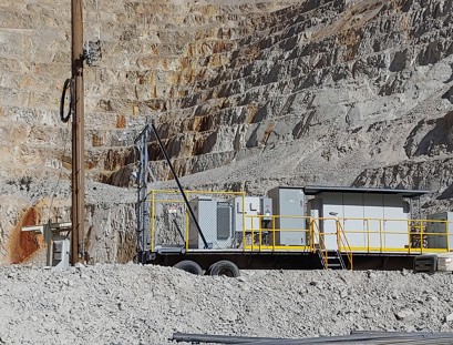
Water presents a significant risk to mining operations, potentially causing equipment damage and environmental contamination. A robust pumping system is required to control the flow of water and remove it from the work site. A large copper mine in Arizona had reached a critical stage where they needed to replace their 250-horsepower (HP) dewatering pump and increase pumping capacity.

DENMARK: Marselisborg Wastewater Treatment Plant went from energy consumer to energy producer by using VLT® AQUA Drive FC 202 from Danfoss. Learn more about that here.
Related applications
Centrifugal pumps and blowers, positive displacement blowers, and variable torque applications.
News

Danfoss VLT® drives now comply with Security Level 1 (SL1), certified according to the standard IEC 62443 4-2. Developed and manufactured under the IEC 62443-4-1 certified process, these drives ensure secure performance from factory to field; balancing risk reduction with usability and safeguarding your infrastructure with industry-leading standards.

Danfoss introduces DrivePro® 360Live: the ultimate data-driven asset management solution designed to transform maintenance practices and empower marine and industrial teams with unparalleled visibility, control, and efficiency.
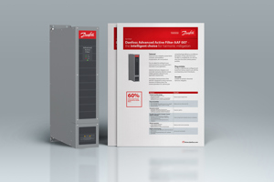
With 60% lower power losses compared to similar filters, Danfoss Advanced Active Filter AAF 007 can rescue your energy budget. Enjoy harmonic mitigation, power factor correction and imbalance compensation, all in one product. This filter is compatible for use with any drive from the entire Danfoss product portfolio.