Join the complete food retail training at Danfoss in Frickenhausen, Germany.
This 3-day program combines theory and hands-on sessions on CO₂ transcritical, subcritical, and booster technologies, advanced controls, and much more — including a factory tour with exclusive insights into compressor technology.
Ideal for refrigeration engineers, system designers, and service technicians looking to strengthen their expertise in future-proof refrigeration. You can find more info on the link below.
Secure your spot

Pack Controllers
AK-PC 551
Programming
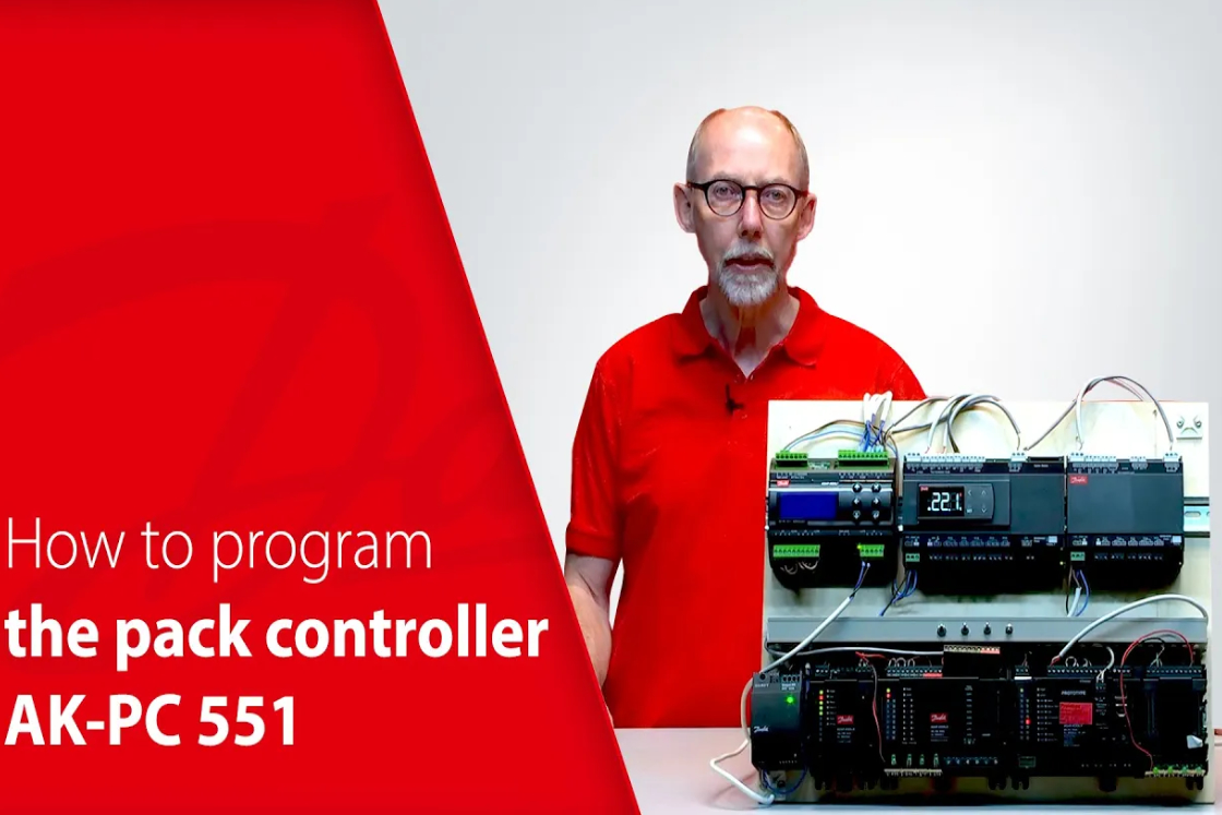
How to program the pack controller AK-PC 551
In this video our product expert Kenn will walk you through how to program the pack controller AK-PC 551
Communication
Condenser
Condenser control
Why is the condenser pressure on the AK-PC 551 not controlled at reference but above reference?
Condenser control using P- or PI-control
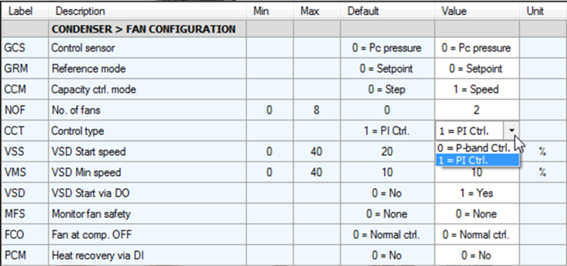
If the condenser control type is set to “P-control” (Proportional control), this control will allow some deviation from the reference, because it is just a P-controller with a P-band allowing a difference between the reference and the controlled value where the size of the difference is depending on the output. P-control is fast but not precise, whereas PI-control (Proportional Integration control) is precise. With PI-control the integration function will, so to speak, integrate the fault away.
The Control Type can be set in the controller. Below it is shown how the control type is changed from P-band control to PI-control using the AK-PT 50 PC software:
Capacity control
Bitzer CRII control
How is the capacity control of Bitzer CRII unloaders working on AK-PC 551?
When the requested capacity reaches the setting of the “Start capacity”, the compressor will start. Start capacity setting for Scroll and CRII is by default set to:
Min: 10%
Max: 60%
Fac: 30%
When the unloader valve goes ON/loads (power to the coil is OFF), the cylinders will deliver capacity.
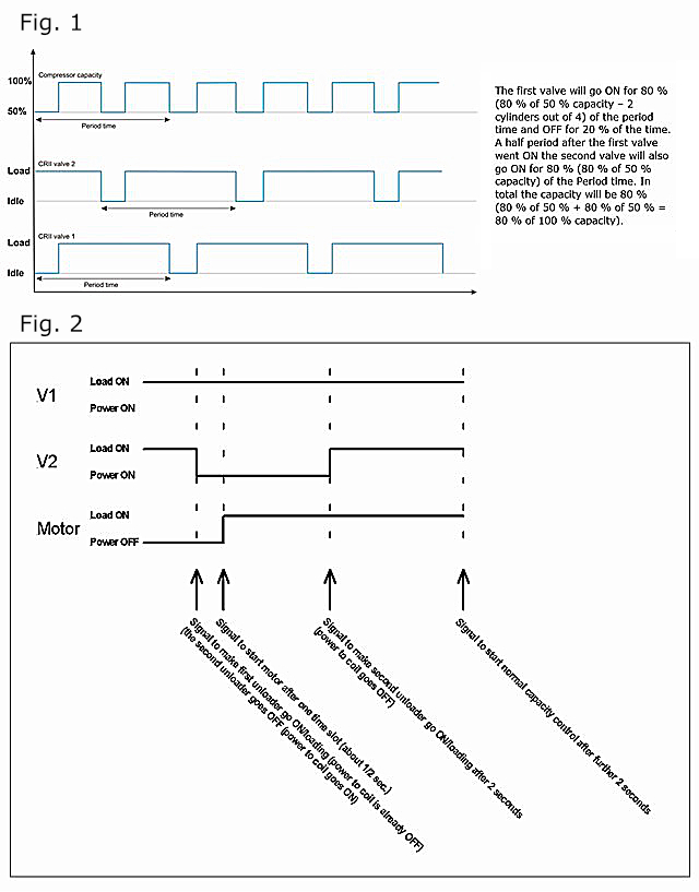
Example with requested capacity of 10 % on a 4-cylinder Bitzer CRII:
2 seconds is 10 % of a 20 second period time and that is for each of the valves controlling 2 cylinders.
The first valve will go ON for 10 % (10 % of 50 % capacity – 2 cylinders out of 4) of the period time and OFF for 90 % of the time. A half period after the first valve went ON, the second valve will also go ON for 10 % (10 % of 50 % capacity) of the Period time. In total the capacity will be 10 % (10 % of 50 % + 10 % of 50 % = 10 % of 100 % capacity).
For fig. 1
- The minimum period time you can set is 10 seconds (nominal is 20 seconds and maximum is 60 seconds)
- The minimum time an unloader valve should be operated in loaded or unloaded state is 2 seconds
With this configuration it is only possible to go down to 20 % capacity. If it is required to go down to 10 % the period time will have to be increased to 20 seconds.
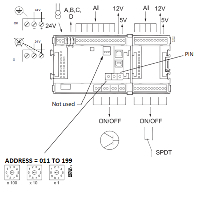
However, the initial start of compressor capacity is a bit more complicated. It is easier to make a sketch (See fig 2)
The unloaders are inversed:
Please be aware that since software version 1.20 of the AK-PC 551 controller (with Packman 2 capacity control) is taking care of the inversion of the unloading valve outputs, the digital outputs should not be inversed for the unloading valves – the controller is taking care of the inversion.
Secondly, please also be aware that whenever a compressor is at standstill, the unloading valve will be without power/loaded. Just before the compressor starts, the unloading valve is powered and the compressor is started (1-2 seconds between these two actions)
AK-PC 651A
Introduction to AK-PC 651A
Our product expert Edivaldo will explain the main differences between the pack controller
In this video our product expert Edivaldo will explain the main differences between the pack controller AK-PC 651 and the successor AK-PC651A

AK-PC 782A/AK-PC 782B
How to replace AK-PC 782A with AK-PC 782B
In this video our product expert Edivaldo will show how to replace the AK-PC 782A with AK-PC 782B

How to connect AK-PC 782B to AK-SM 800A
In this video, our product experts Edivaldo and Premnath will show how to connect AK-PC 782B to AK-SM 800A

How to use the AK-PC 782A/B for controlling Heat Recovery
In this video, our product expert Edivaldo will look at how to use the AK-PC 782A/B for controlling Heat Recovery.

What addresses can I use in my new AK-PC 782B to communicate with the System Manager?
The AK-PC 782B was designed to use Ethernet connection to the System Manager, through the router – check the video “How to connect AK-PC 782B to AK-SM 800A” in this webpage for connection details.
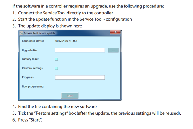
To configure the network address of the AK-PC 782B, the valid range of addresses is between 011 to 199, as shown below in the Installations Guide and User Guide:
The AK-PC 782B was designed to operate in this range of addresses. However, if by mistake the address is set to 001 to 010, the AK-PC 782B might not be able to communicate properly with the System Manager.
For further information, please visit the following document.
IP communication system Pack Controller
Pack Setup
Miscellaneous
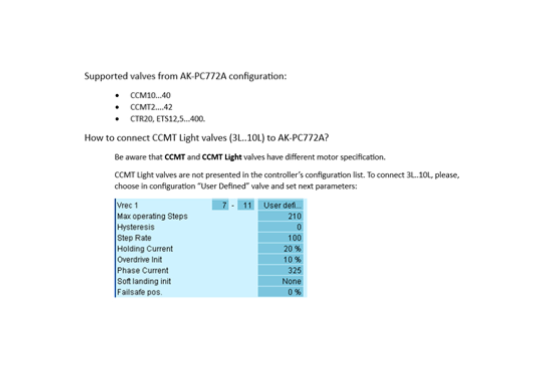
How to update a pack controller based on AK2 platform (AK-PC 772A, AK-PC 78xA, etc)
The image below comes from the AK-ST 500 manual:
How to choose the proper flash file to update your AK-PC controller?

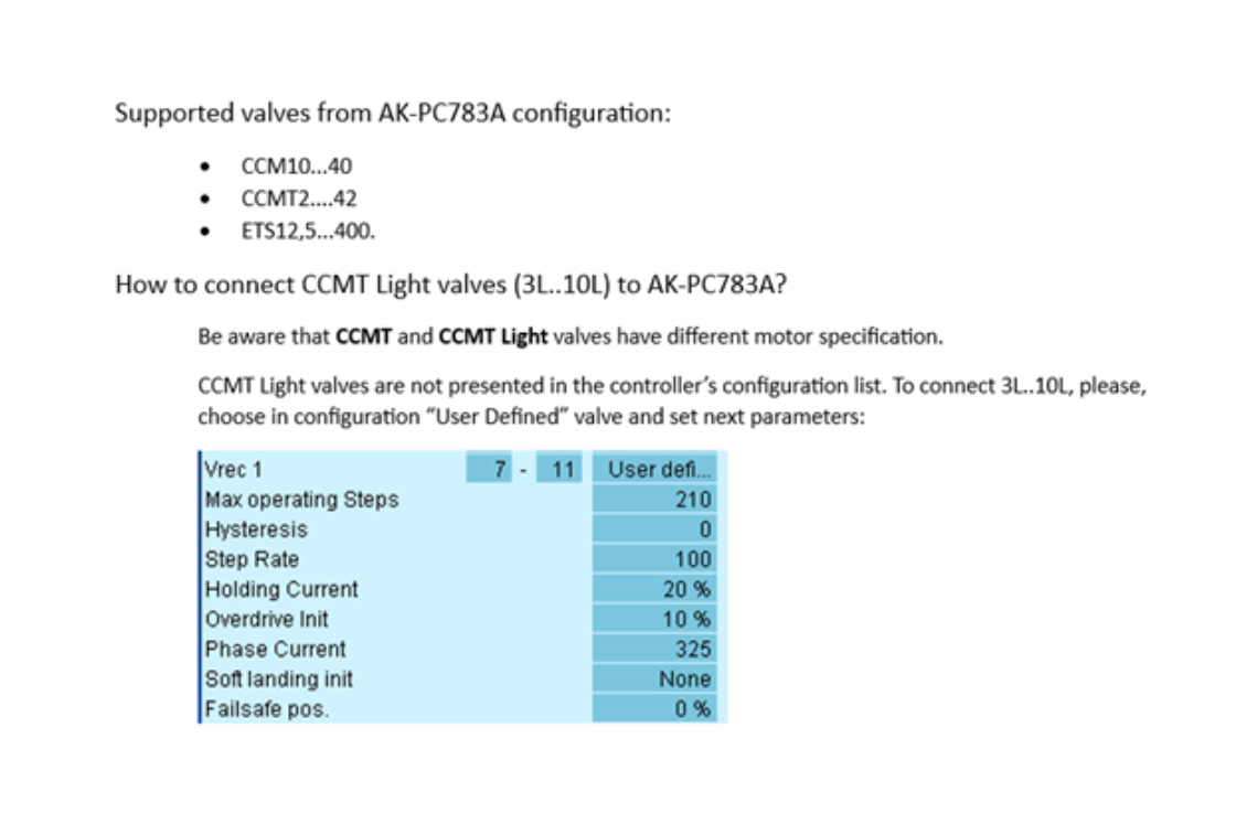
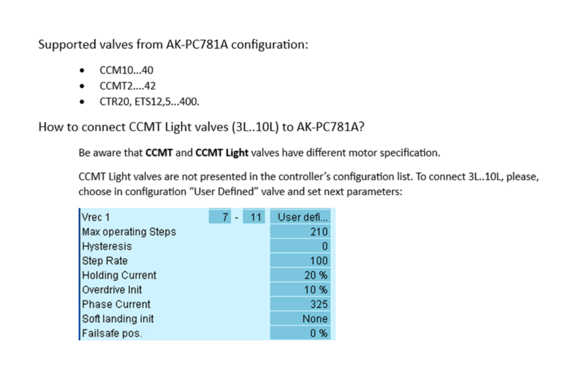
How to configure different stepper valves in the pack controllers
Configuration of Danfoss stepper valves:
AK-PC772A
AK-PC781A
AK-PC783A