Maximizing the potential of Si and SiC power modules
To power up the fast-growing fleet of HEVs, PHEVs and BEVs, Danfoss has developed a power module technology platform, DCM™1000, for traction applications.
With silicon (Si) and silicon carbide (SiC) being the main cost-drivers in power modules, our DCM™1000 platform aims at reducing the semiconductor surface enabled by combining our winning patented technologies.
Your DCM™1000 benefits
-
Customizable to your exact needs
-
Combining of winning technologies for higher performance
-
Maximizing the potential of Si and SiC
-
Scalable across voltage classes
FAQs about the DCM™1000
What is meant by the given current rating of DCM™ modules?
First of all, DCM™1000 refers to a package size offering footprint to assemble a semiconductor area of 1000mm².
Second, current ratings strongly depend on applied boundary conditions such as cooling parameters and DC-link voltage. The current rating for the DCM™1000 considers nominal operation points at customers' side.
Is DCM™ 1000 scalable for several power classes?
Adjusting both chip content and DBC substrate materials, we are able to offer several power classes within the DCM™1000 package. This allows customers to use power modules having the same outer dimensions for traction inverters with different output power without the need for a re-design. This accounts for both DCM™1000 (750V) and DCM™1000X (1200V). The suffix “X” stands for the extended clearance and creepage distances for applications with up to 1000V DC link voltage. Nevertheless, both the DCM™1000 and DCM™1000X can utilize Silicon Carbide MOSFETs.
Which semiconductors are inside the DCM™?
The DCM™ is a technology platform which means that all types of automotive qualified semiconductors can be housed. For 400V and 800V drive train inverters, typically Si IGBTs and SiC MOSFETs can be assembled. It is possible to use advanced bonding and joining technologies such as DBB® with either copper wire bonds or copper ribbon bonds.
How do differences between chip suppliers challenge the inverter design?
Danfoss has a unique business model and one of the main pillars is chip independency. This means that we are free in the choice of power semiconductors. Of course, even if designed for the same power class, semiconductors from different manufacturers vary in terms of e.g. internal gate resistor, gate charge or even breakdown voltage. For many suppliers, this can challenge the design of the inverter.
However, we have thoroughly assessed the differences and can fully support customers during the design of the inverter and the driver board when it comes to a change of the favored semiconductor manufacturer or if a second source approach is needed. In addition, the low module stray inductance of below 7nH allows the usage of different semiconductors with various breakdown voltages.
How can the modules be mounted? Are there different options?
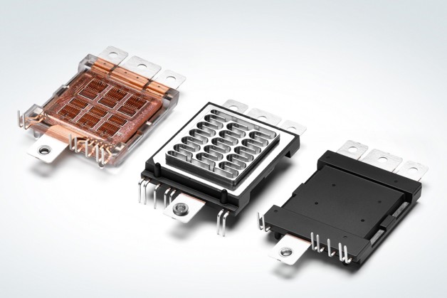
The modules are mounted to the cooler by using clamping brackets screwed directly to the cooler. The brackets have direct contact to the available area at the top of the baseplate, shown in Figure 2. There are different concepts available that can apply sufficient pressure for the sealing gasket located close to the orders of each half-bridge.
Danfoss proposes concepts with either two M4 screws or just one M5 screw on each side of the power module. In advanced designs using an aluminum cooler, the total number of screws can be reduced to 4 instead of 8 in typical 6-in-1 module designs.
How does the cooling concept work?
The cooling concept of DCM™ platform utilizes the patented ShowerPower®3D cooling technology. The baseplate of the power module has meandering channels guiding the coolant and creating powerful swirl effects that washes the boundary layers away thereby maximizing the cooling efficiency. In spite of the swirl effect, the flow is laminar therefore the pressure drop is very low and mainly influenced by the design of cooler in- and outlet and the bypass across the structured baseplate. The final thermal resistance relates to the selected power class, i.e. silicon area and substrate material. The customer designs the bathtub of his cooler according to the interface needed for the DCM™1000 power modules.
Danfoss can provide all necessary drawings and a reference design from our application-kit.
When can we get started with the DCM™ platform?
During early development of a traction inverter, customers will need a complete package of materials for designing purposes and to assess the performance of the power module during operation. Therefore, Danfoss provides datasheets, CAD files of the module, drawings including the interface to the cooler and detailed application notes. To make testing fast and easy, we offer an application-kit including DC-link capacitor, driver-board and cooling, providing the possibility to directly test the DCM™ 1000 modules in the laboratory.
Danfoss engineers custom SiC and IGBT power modules to help you meet stringent reliability, design and cost targets.
Read more