Hot gas defrost of low temperature refrigeration evaporators with natural refrigerants

Monday, December 3, 2012

Industrial refrigeration systems predominantly use natural refrigerants, primarily ammonia and more recently CO2. Energy efficiency and the effective operation of those systems are the key parameters for operators of the plants.

The focus of the white paper is the comparisons of hot gas defrost strategy control methods, both on the hot gas side as well as on the condensate drain. 

This white paper is based on the article originally presented at 10th IIR Gustav Lorentzen Conference on Natural Refrigerants, Delft, the Netherlands, 2012.

Industrial refrigeration systems predominantly use natural refrigerants, primarily ammonia and more recently CO2. Energy efficiency and the effective operation of those systems are the key parameters for operators of the plants. The focus of the article is the comparisons of hot gas defrost strategy control methods, both on the hot gas side as well as on the condensate drain. The key parameters analyzed on this paper are the efficiency as well as the speed of defrost, which is especially important for the productivity of the freezing plant.

Authors suggest opportunities to improve controls for hot gas defrost systems. The article describes hot gas defrost for ammonia systems, indicating special requirements for CO2 plants where relevant.

Some of those requirements are derived from higher pressures and higher pressure differentials with CO2. The article indicates that when defrost is performed in an optimal way could save up to 5%of the plant energy consumption or even more. 

This white paper is based on the article originally presented at 10th IIR Gustav Lorentzen Conference on Natural Refrigerants, Delft, The Netherlands, 2012.

As far as air-coolers are concerned, defrost is the “inevitable evil”. The frost needs to be melted, or it will severely impact the performance of an air-cooler, and eventually could totally block the air flow. There are several negative implications associated with hot gas defrost. Additional compressor energy is required to melt the frost/ice layers formed around the evaporator’s fins and tubes. At least, a part of this energy is transferred back to the refrigerated space or heats up the evaporator. It eventually needs to be removed during the cooling process. Finally, the time used for defrost is not used for cooling. This could be a very important factor in food processing plants, where defrost could significantly limit productivity levels. In addition, other important but less obvious consequences may undermine integrity such as the mechanical stress undergone by key components. A lot of failures found on valves and controls used around evaporators may be attributed to wrong valve configuration and or settings. 

The main source of mechanical stress is the combination of high pressure coming from the condenser side, high discharge temperature and high pressure differential. When combined, those factors could be quite dangerous and even destructive. Today we also see that there is an increased number of companies using CO2 for low temperature plants, and quite often in combination with hot gas defrost. At the same time, the situation with CO2 in this case is even more complex than with ammonia, as the pressure level and pressure differentials are much higher. The complications of hot gas defrost with CO2 may have caused some customers to avoid this kind of defrost method and look for other alternatives, such as electrical or brine defrost. 

Hot gas defrost is one of the most efficient ways to melt the frost formed on an evaporator (Pearson, 2006). As there is an increased focus on the reduction of energy consumption, performing a quick and efficient defrost is key to achieving overall energy consumption goals of the refrigeration system. In most cases, it would be also the most cost effective way when compared to e.g. brine defrost. This article focuses on valves and controls configurations that could be applied for such systems as well as the ways to optimize the process.

There are a few studies targeting the understanding and improvement of hot gas efficiency of refrigeration systems. A number of the critical points could be summarized as follows:

1. Hot gas defrost pressure. A popular misconception is that the higher the defrost temperature, the better. In reality a number of studies indicate (Stoecker, 1983) that a source of lower pressure and temperature gas could obtain good results as well. There is most likely an optimal pressure / temperature (Hoffenbecker, 2005) that would achieve the highest efficiency.

2. Hot gas defrost time. In the industrial refrigeration, it is very typical to set up defrost based on a fixed time adjusted during the start-up of the installation. The problem with this approach is that in many cases this time would be on a “safe side” to ensure having a fully clean evaporator. What happens in reality when the defrost is finished earlier, is that the efficiency of defrost significantly drops.

3. Another significant inefficiency during the hot gas defrost could be contributed to the vapor passing through the defrost pressure regulator. This vapor needs to be recompressed, and it also increases the requirement for the hot gas feed to the evaporator. The amount of vapor passing is depending of the type of defrost control in the condensate line. Pressure controlled or liquid level controlled.

4. The amount of energy used for melting the ice during the defrost is more than double (Stoeker, 1983, Hoffenbecker, 2005) of what is actually needed to melt the ice. The rest of the energy goes for heating the space, evaporator, tubing and the drip pan.

5. Finally, it should be mentioned that the ice is first melted on the coil, then the ice crashes in to a drain pan and then finally melts completely.
What is important here is that the process is sequential; with initially higher demand for defrost in the coil, and only later in the drain pan.

6. When the hot gas defrost is started, the initial refrigerant inrush might create a liquid hammer, especially if the evaporator still has some liquid refrigerant that has not been drained. This also occurs if the hot gas supply lines contains pockets of condensed liquid being propelled by the supplied hot gas pressure, and gas pockets to implode. 

Let’s consider those issues in relation to the valves and controls used to control a hot gas defrost process. 

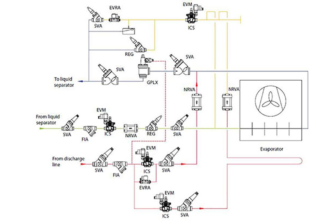
Fig. 1 presents a typical industrial refrigeration evaporator with hot gas defrost. Control valves for the evaporator could be divided in the 4 main groups:

1. Pumped liquid feed to the evaporator. This valve train typically includes stop valves, filter, a solenoid valve, a regulating valve, a check valve and a final stop valve.

2. Hot gas feed line. Traditionally it has a stop valve, a filter, another solenoid valve and a stop valve 

3. Condensate line. Here we either see a pressure controlled valve or a float principle to drain the liquid. Both significantly different defrost principles as we see later.

4. Wet return line. This line needs to have an automatic shut off valve and a stop valve. 

The defrost process could be divided into 4 main sections. First, the liquid supply to the evaporator is shut off. Evaporator fans should still run for sometime, suction valve remains open in order to make sure that remaining liquid refrigerant will boil out. Second, the suction valve will be closed, evaporator fans will be stopped, the hot gas solenoid valve will be opened and the feed of the evaporator with the hot gas starts. Thirdly, when the defrost is finished, the hot gas solenoid valve will be closed, the suction valve will be opened. Finally, the liquid feed is opened again, water droplets on the evaporator fins are allowed to freeze , and only then the evaporator fans will be started again.

Critical considerations in the hot gas defrost process are avoiding pressure/temperature stresses and system inefficiency by managing a slow pressure built up in the cooler at the start of defrost and at the same time a slow pressure release from the cooler after the process. Both hot gas solenoid and main suction valve selection are critical when aiming for a safe and efficient defrost process.

Considering the efficiency considerations indicated above, let’s review the traditional valves configurations. It should also be considered, that the defrost with CO2 is a more harsh one, and a conservative approach for CO2 evaporators with hot gas defrost should be preferred.

Figure. 1 Typical configuration for an industrial refrigeration evaporator with hot gas defrost.

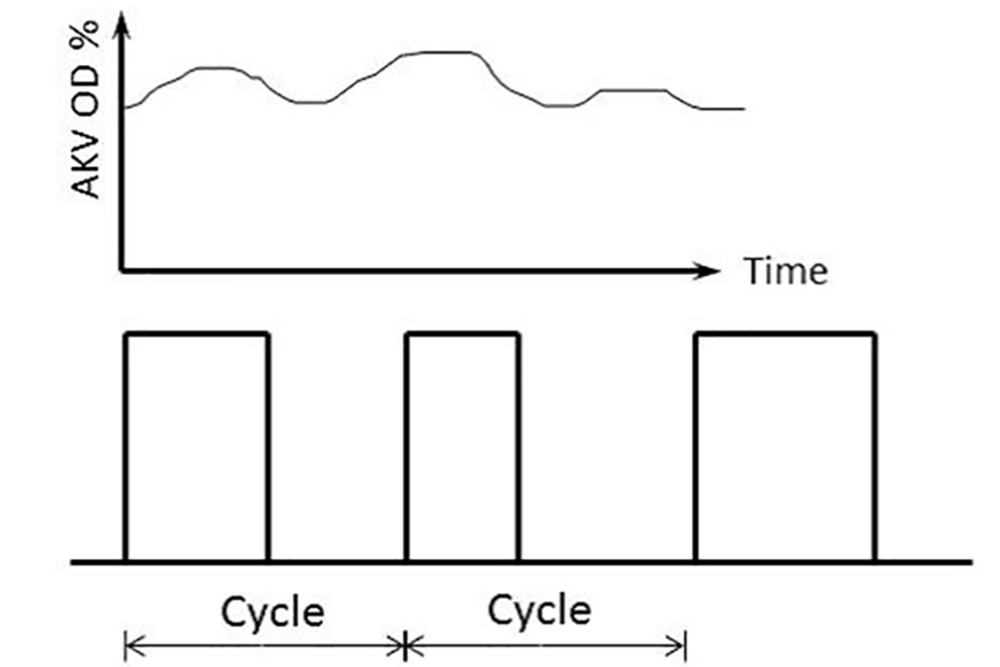
Liquid feed line has the minimal influence on the hot gas defrost process. What could be important to consider here, is the amount of liquid that is fed to the evaporator. In case PWM (pulse width modulation) strategy is used, the amount of liquid refrigerant in the evaporator will be lower. That should reduce the time needed to get rid of the liquid refrigerant. It could also be expected that the amount of ice is lower as well, as the temperature deviation on the surface in on/off periods is lower (figure 2). 

This liquid feed strategy has been successfully used in a number of CO2 systems with pumped re circulation. In ammonia systems, this control method has not been widely applied yet.

Figure 2. Pulse width modulation liquid feed

The most common way to feed hot gas in an evaporator, is with a conventional solenoid valve. Motorized valves and motorized ball valves have also been used for the purpose, especially for CO2 systems. With higher pressures, and higher pressure differentials, the risk of liquid hammer in CO2 hot gas defrost systems is higher than with ammonia. Clearly, the downside of the solution with motorized valves is that they are more complex to set up, and valve trains with motorized valves are more expensive than traditional ones.

Another point, which is especially critical for the ball valves, is that the opening speed must be adjusted to a relatively low level. A solution with 2 solenoid valves, the first sized for the required hot gas defrost capacity, and the second for 10-20% of the flow and installed in parallel to the first one (Figure 3) could be more cost effective and efficient. The smaller solenoid opens first and feeds the evaporator with hot gas for the first few minutes, increasing the pressure in the evaporator and supply lines in a controlled way. After that the second solenoid opens and the main defrost starts. This valve train configuration has already been used in a number of installations and in general proved to be successful.

The benefit of the motorized valves in hot gas defrost lines is that they make it possible to have an intelligent hot gas control. That may include not only slow opening, but slow (or adjusted) closing as well. That could be relevant in those cases, when the defrost is not done based on timing, but rather on other parameters, such as surface temperature control.

Finally, in order to limit the hot gas pressure / defrost temperature and maximize the defrost efficiency; a downstream regulator could be installed. It is only necessary to install one such regulator for a group of evaporators connected to the same hot gas line. The sizing of the valve should be such that it can provide enough hot gas for all evaporators that might be defrosted at the same time.

Figure 3. Hot gas feed line with double solenoid valve 

There is a wider variety in the regulation devices, used in condensate lines of evaporators with hot gas defrost. Differential pressure regulators are quite common, but upstream pressure regulators and float valves are applied as well. As discussed, the float valves are expected to be the most efficient controls for the hot gas defrost. A combination of float valve in condensate lines with downstream pressure regulators in hot gas lines would be a preferable one, in order to make sure that the defrost pressure is kept on the optimal level. 

There are downsides of the solution with float valves as well. First, the cost could be relatively high. The cost might be partly reduced by installing a float regulator in a common evaporator condense line for several evaporators. Secondly, for high pressure refrigerants, such as CO2, float regulators are difficult to find. In this case alternatives must be explored. One of them is steam traps, which are coming from other industries, and can manage high pressures. Even though steam traps are gaining popularity, those devices are not very common in the refrigeration industry yet. Their specifics won’t be discussed further in this article, however, all considerations valid to float valves used in condensate lines, should also be applicable to steam traps.

Figure 4. Float valves in condensing lines with multiple evaporators. Only valves in the condensing lines are indicated.

Control valves used in wet return lines are solenoid valves, gas powered solenoid valves (both of them need to have a bypass valves to avoid liquid hammering after defrost), 2 step gas powered solenoid valves as well as motorized valves and motorized ball valves. Preferred options are either 2 step gas powered solenoid valves or motorized valves. On one hand they help avoiding liquid hammer, either because of the 2 step function, or because of the slow opening speed. On another hand, they give minimal pressure drop during the cooling cycle, which is especially critical at low temperatures. 

An advantage of the 2 step gas powered valves is that they require no additional settings. The second stage opens automatically when the pressure difference over the valve drops below certain value. Motorized valves require speed adjustment, but have no need for an additional hot gas line to power them. Motorized valves are especially popular for CO2 systems, as they are easier to get for higher pressures. Ball valves with a bypass solenoid valves are frequently used as well. The benefit of the solution is the low pressure drop during the cooling cycle. However the leak possibility over the stem is a cause for concerns.

In order to get an understanding of the efficiency improvement of the optimized defrost control against a conventional one, an example for the industrial refrigeration cold store has been calculated. The main parameters of the analyzed coldstore are summarized in the table 1.

Table 1. Main coldstore data


The defrost calculation for the system in question was done in 2 steps. Firstly, the necessary energy for melting the ice and removing the water has been calculated. The calculations were done in a similar manner as Pearson (2006). The blockage of the air passage between the fins is assumed to be 20%, which with fin spacing of 10 mm results in 1 mm ice thickness. Ice thickness is one of the parameters that has a big influence on the defrost efficiency. Higher frost thickness improves the efficiency of defrost, but negatively affects the efficiency during the cooling process. It is out of the scope of this article to find an optimal ice thickness.

 Table 2. Ice melting energy calculation


Parameter
Value
Dimension
Fin Spacing
10.00
mm
Ice Thickness
1.00
mm
Evaporator
100
kW
Weight
580
kg
Frost density
300
kg/m3
Surface area 
450
m2
 Frost weight
 135.00
kg 
 Start temperature
 -35
°C 
 End temperature
 5
 °C 
Specific heat ice
2.1
kj/kg*k
Specific heat water
4.2
kj/kg*k
Specific melting heat
336
kj/kg
Energy to heat the ice to 00C
9,922.50
kj
Energy to melt the ice
45,360.00
kj
Energy to heat up water to 50C
2,835.00
kj
Total heat required to melt ice
58.117.50
kj
 

The calculation was done for a standard industrial refrigeration evaporator from one of the major manufacturers. Energy losses during defrost are not included in to this calculation. According to Hoffenbecker (2005), the losses during defrost are on the level of 55% or more for lower defrost efficiencies. The losses depend on the defrost time and temperature, as well as on the frost thickness.

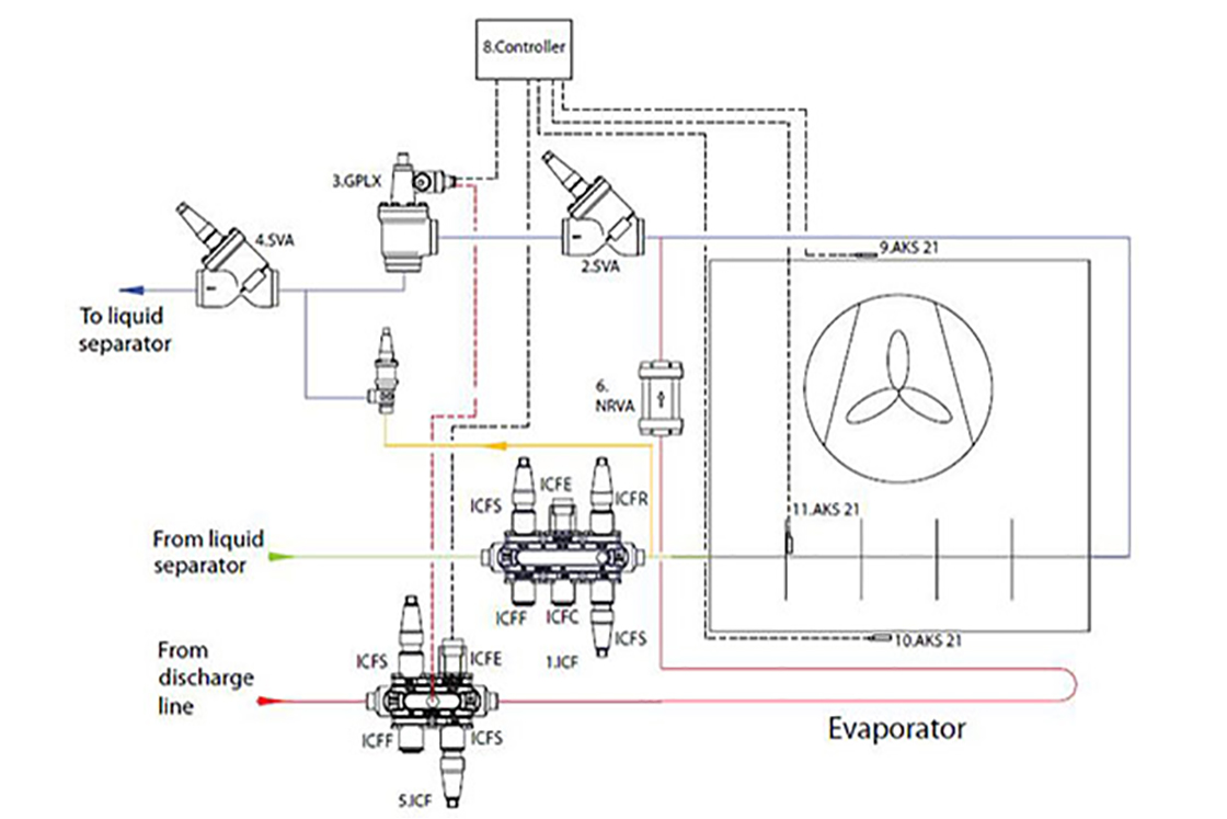
Assuming that for an optimized defrost process the losses are on the level indicated by Hoffenbecker (2005), as a second step of the defrost analysis let’s have a look at the comparison with a non-optimized evaporator. The main figures for this comparison are presented in table 3. Piping diagram for a standard system is presented on figure 1, and for an optimized on figure 5.

Table 3. Defrost efficiency comparison

The calculations are based on a number of assumptions, and are done for a specific system only. However they indicate that not optimal hot gas defrost could not only create problems with the equipment, but also result in a power consumption increase. Table 4 presents the data summary, as well as an evaluation of the financial impact of not optimized defrost.

Table 4. Extra costs of not optimized defrost

It is clear, that the more defrosts are needed, the higher the importance of the right valves configuration around the evaporator. If for some coldstores with weekly defrost the additional energy impact is minimal, for some freezing equipment with several defrosts daily an additional energy bill could be on the level of 5% or more of the energy consumption of the refrigeration equipment. And that is not considering the worst systems, with higher condensing temperatures to keep the defrost temperatures high.

The calculation above is mainly valid for an ammonia system. In case of CO2, and additional defrost compressor should be used, which will obviously change the energy balance. As in case of ammonia systems, a general increase of the condensing pressure on main compressors is not recommendable.

Figure 5. Optimized defrost system configuration

The article made an overview of different control possibilities of hot gas defrost systems. Different options available today were compared with a number of analysis made, and preferable options were indicated. The main conclusion of this analysis is that if defrost is made in an optimal way, potential energy savings on the level of 5% or more of the total energy consumption of the system could be realized. The comparison is made with common systems used today. In case some of the worst case (and still not rare) examples are taken, the overall potential looks even bigger. 

Further practical tests to confirm theoretical conclusions were started. However they were not finalized by the time the article was made and are subject to a further research.

Industrial Refrigeration
SVL Flexline™

Hoffenbecker N., Hot Gas Defrost Model Development and Validation, International Journal of Refrigeration, January 2005

Pearson A., Defrost Options For Carbon Dioxide Systems, 28th Annual IIAR Meeting, March 2006

Stoeker W.F., Energy Considerations in Hot-Gas Defrosting of Industrial Refrigeration Coils, ASHRAE 1983