Join the complete food retail training at Danfoss in Frickenhausen, Germany.
This 3-day program combines theory and hands-on sessions on CO₂ transcritical, subcritical, and booster technologies, advanced controls, and much more — including a factory tour with exclusive insights into compressor technology.
Ideal for refrigeration engineers, system designers, and service technicians looking to strengthen their expertise in future-proof refrigeration. You can find more info on the link below.
Secure your spot
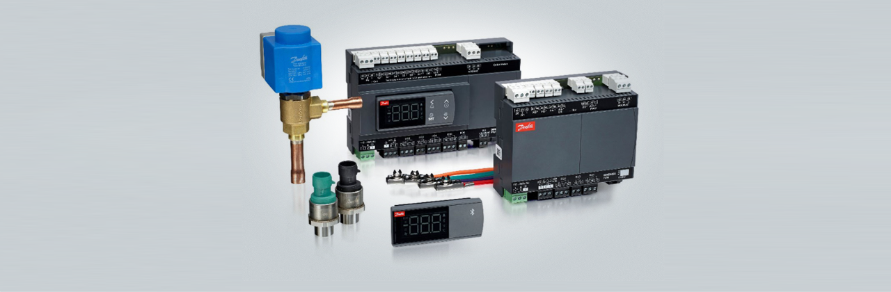
Case Controllers AK-CC25
Cyber security
Access codes
Factory reset
Case Controller AK-CC55
Defrost
Hot Gas Defrost sequence-AK-CC55
How is the hot gas defrost sequence on AK-CC55 managed?
In this video we will show an animation of the hot gas defrosting procedure using a Danfoss AK-CC55 single coil controller.
Here the Hot Gas Defrost sequence for case controller AK-CC55 is described.
The principle and sequence of hot gas defrost is also used in many other types of case controllers like AK-CC 200/300/450/550/750. Some controllers have solenoid valves instead of AKV valves and some do not have drip tray heaters. Apart from that the sequence is the same.
The outputs on the AK-CC55 used in the hot gas defrost sequence are (Application 5):
- AKV valve
- Hot gas valve
- Drain valve
- Suction valve
- Fan
Evaporator 1: This will finish defrost first in a coordinated defrost sequence
Evaporator 2: This will finish defrost last in a coordinated defrost sequence: (In this example max. hold time expires immediately after defrost stops. The max. hold time should be set to the same time as max. defrost time)
d16 – Pump dwn del. (Pump down delay):
Set the time for when the evaporator is emptied of refrigerant prior to defrost.
d23 – HotGasInjDel (Time delay before opening of hot gas valve):
This allows time for a PMLX valve in the suction line to close (if used).
d04 – Max Def. time (Max. defrost duration):
This setting is a safety time stopping the defrost if there has not already been a stop based on temperature or via coordinated defrost.
o16 – Max HoldTime (Max. standby time after coordinated defrost):
When a controller has completed a defrost, it will wait for a signal telling that the refrigeration may be resumed. If this signal fails to appear for one reason or another, the controller itself will start the refrigeration when this standby time has elapsed.
d17 – Drain del (Drain delay (only in connection with hot-gas)):
Set the time for when the evaporator is de-pressurized and emptied of condensed refrigerant after the defrost.
d06 – DripOff time (Drip-off time):
The time that has to elapse from the hot gas valve is closed and until the injection may start again (the time when water drips off the evaporator). This function is normally not used together with hot gas defrost – drain delay will normally take care of drip off too.
d07 – FanStartDel (Delay of fan start after defrost):
The time that has to elapse from injection start and until the fan may start again (the time where liquid water drops are freezes onto the surface of the evaporator).

Fan
ECO function in AK-CC55
Injection
Adaptive Liquid Control function for AK-CC case controllers
How do I exchange an AK-CC 550 with an AK-CC55?
Exchange of an AK-CC 550 with an AK-CC55
Learn how to replace the AK-CC 550 with the AK-CC55. In this video, Kenn Sønder Jensen guides you through replacing the AK-CC 550 with the AK-CC55. Discover how easy it is to replace the controller, what you should be aware of when doing so, and how to avoid pitfalls.

Exchange of controller
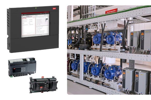
Showing you how to replace an AK-CC 550A with an AK-CC55, product expert Premnath Kangatharan guides you through the steps you need to know to effectively change your case controller in the interface of the AK-System Manager 8xxA series. Get familiar with the new System Manager interface and ensure you get your new case controller up and running quickly.
Miscellaneous
Technical data
DO relays for capacitive loads – AK-CC55
User interface
Communication Status U45 checks signal quality for MODBUS-AK-CC55
Introduction to the AK-CC55 Connect App
How to set up the AK-CC55 Connect App?
In this video, our product expert Paul will look at how to set up the AK-CC55 Connect App.

Wiring
Display cable length for AK-CC55
AK-CC55 Water Loop Controller
Introduction to the AK-CC55 Water Loop Controller
In this video our product expert Kenn will give an introduction to the AK-CC55 Water Loop Controller.