Here is how that works:
Information about the current pressure within the system is generally passed to the pressure switch via a separate spur pipe, but if the pressure switch is mounted directly on the main pipe (cartridge pressure controls) there will be no need for this. In either case, the pressure activates a floating contact system that (e.g.) switches the compressor off in an emergency.
Function of a pressure switch
Let us begin with the function of the low-pressure switch in a heat pump. Low-pressure switches are usually installed close to the compressor on the suction side and are most commonly used as a protective cut-out for the compressor when the refrigerant is low. The reason for this is that losing refrigerant can cause a number of different problems for the system. For example, it reduces suction gas cooling, which is a major problem, particularly for compressors with 100% suction gas cooling. Such a leak will also always lose refrigeration oil – because this circulates through the entire cooling circuit together with the refrigerant – and this may result in inadequate lubrication. As a precautionary measure, to prevent the compressor being damaged or even failing completely, it is therefore highly advantageous to switch it off whenever the low pressure value drops sharply. To be sure, not every activation of a protective low-pressure switch necessarily implies low refrigerant. In such cases the service technician should always check the medium throughput at the evaporator. If some other fault is bringing this down there may be no lack of refrigerant. One simple example of this is a defective evaporator fan in an air to air or air to water heat pump, or a defective pump on the evaporator side in a water (brine) to water heat pump.
Pump-down circuits
Low-pressure switches can also be used as regulators. In “pump down” and “pump out” circuits they are used to switch off the compressor whenever the room thermostat switches off (e.g. when its switch-off temperature is reached). In this case, the liquid line solenoid valve is closed but the compressor initially continues to operate so that the pressure from the liquid line solenoid valve is “pumped down” via the evaporator to the suction side. At a specific threshold value the low-pressure switch then switches the compressor off. If the regulating thermostat subsequently reaches its switch-on point and opens the solenoid valve, then the pressure in the suction line will rise. When it reaches the switch-on point of the low-pressure switch, this will switch the compressor back in.
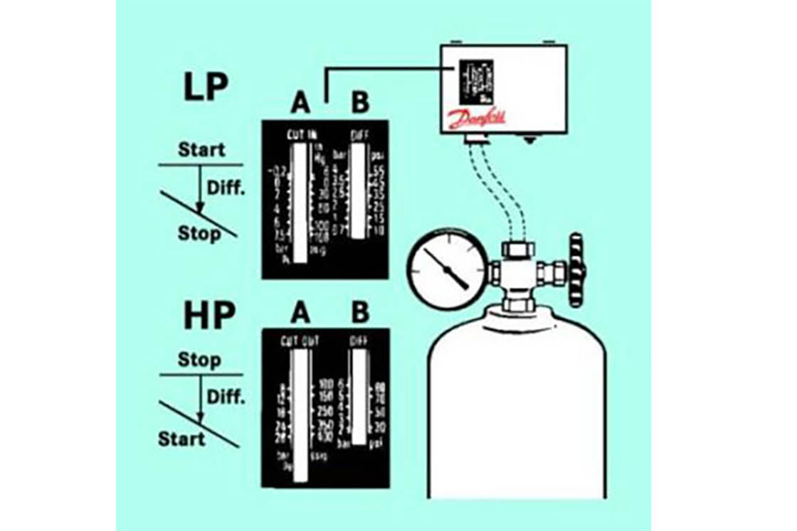
Pressures
When choosing or replacing pressure switches it is important to pay particular attention to the pressures involved. For example, it is important to know the maximum working pressure in order to decide whether a given pressure switch is in any way suitable for the particular application. This means that you should therefore use only high pressure switches that are rated with the maximum working pressure specified by the manufacturer for the specific heat pump. As a rough guide to the pressure ranges that occur with the various refrigerants, consider the pressures at a condensing temperature of 60°C.
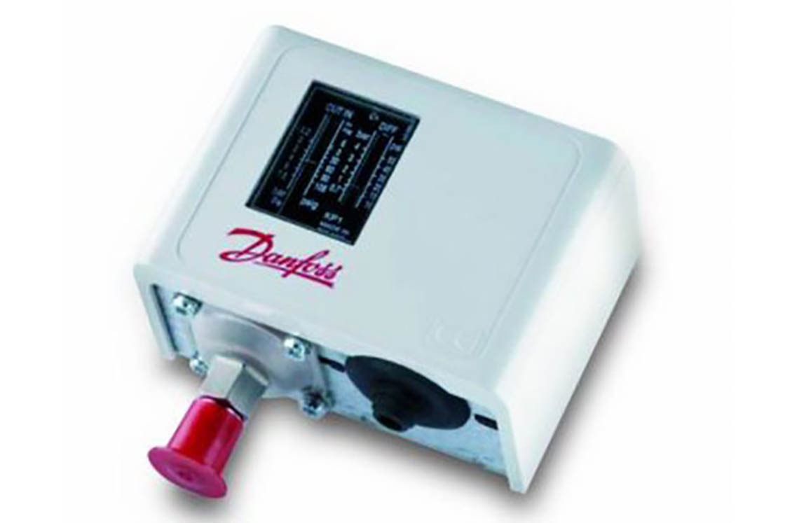
If you need a higher compression temperature, for instance in old buildings with cast-iron radiators, then you will need to choose a higher maximum working pressure. At 60°C the refrigerant R134a will be at an overpressure of around 16 bar, R407C (dew point) at 24 bar and R410A at 37.5 bar. If you have any doubt you should choose a slightly higher value for the maximum working pressure rather than one that is too low. Another important question is the value at which the pressure switch actually activates. An adjustable pressure switch offers a range of values that will normally be sufficient for any purpose. For instance, the adjustable pressure switch KP 6 has a range of from 8 to 42 bar (gauge pressure) for a maximum working pressure of 46 bar. In other words the maximum high-pressure setting is 42 bar, which is quite useable for R410A or in less critical applications for R744 (CO2). For service use – e.g. as on-board equipment for Service vehicles – we recommend adjustable pressure switches with a high maximum working pressure, because they can be used to service almost any heat pump with a variety of refrigerants.
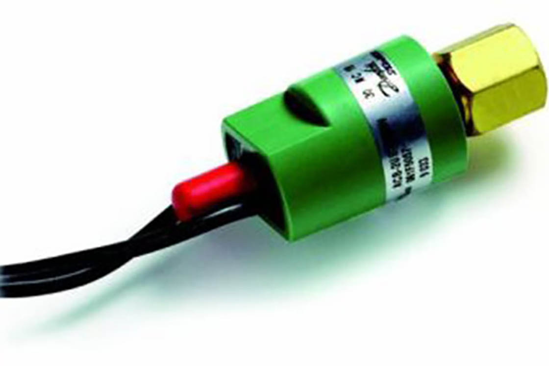
For cartridge pressure controls it is necessary to pay particular attention to the switch points, because their threshold values are fixed and cannot subsequently be changed. If you see, for example, a cartridge pressure switch of type ACB with a label that reads “26 NC 20 bar PS 45 bar”, this signifies a switch-off pressure of 26 bar, a reactivation pressure of 20 bar and a maximum working pressure of 45 bar. The abbreviation “NC” here indicates the direction of operation of the high pressure switch, the corresponding abbreviation for a low pressure switch would be “NO”. You can also recognize a low pressure switch by its low switching point – e.g. “1.5 NO 0.5 bar”. There are also “NO” cartridge pressure controls with relatively high pressures (e.g. “16 NO 13 bar”). These are not suitable for heat pumps because their use is restricted to the regulation of condenser fans in refrigeration units.
Electrical connections
Unlike adjustable standard pressure switches, cartridge pressure switches usually have only single floating contacts (just settings for “open” and “closed”, no system for switching over from one contact to another). In a standard pressure switch with a changeover contact system there are normally three contacts for connecting to the separate cores of the power cable. These three connections are “phase input”, “fault” and “phase output (to the motor)”. For dual connections to “phase input” and “phase output” it makes no difference if the two connections are exchanged or confused.The “fault” connection is not generally used, but could activate a red light or forward a signal to a remote maintenance center.
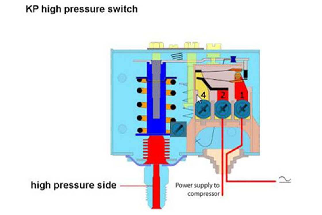
In the Danfoss KP1 (low pressure switch), “phase input” is connected to contact 1 and “phase output” to contact 4. If the “fault” function is needed it can then be connected to contact 2. Please note that the connections for Danfoss KP7 high pressure switches are not the same: while “phase input” remains on contact 1, “phase output” is on contact 2 and contact 4 becomes the fault signal. This may seem confusing, but the service technician can easily figure it out by examining a KP pressure switch. If you remove the plastic cover you will see the contact system on the right-hand side labelled “1”, “2” and “4”. On the low-pressure switch KP1, contact 4 is on top with contact 2 underneath. Here the cut-out situation occurs when the pressure drops (e.g. low refrigerant). Since the bellows element of the pressure switch always moves upwards as the pressure increases (and the bellows inflates) and down as the pressure drops, the switchover has to be effected by a downwards movement. This means that on the KP1 you select contacts 1 and 4 for the mains-compressor path. Conversely, on KP6 and KP7 high-pressure switches, the cut-out has to be effected when the bellows moves upwards. Since contact 4 is still at the top and contact 2 still at the bottom, the connections here have to be on contacts 1 and 2. With one exception (the KP7BS, which comprises the two high pressure switches DBK and SDBK) dual pressure switches from Danfoss are always a combination of a low-pressure and a high-pressure switch; there are variants with only low-pressure or with low-pressure and high-pressure alarm contacts. Dual pressure switches do not call for any electrical installation or mounting work, and two pressure switches will generally cost more than a single dual pressure control.
Pressure connection
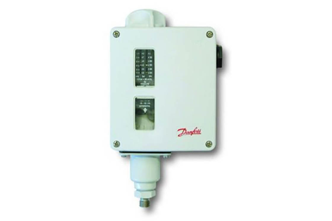
If you use a wall-mounted pressure switch for a refrigeration plant you should be particularly aware that safety high pressure switches (such as the KP7W, KP7B, KP7S and KP7BS) are always connected via a stub pipe of at least 4 mm internal diameter, in other words a 6 mm copper pipe. Naturally, it is also possible to use special plastic pipes with internal diameters of at least 4 mm for heat pumps or refrigeration plants. Low pressure switches may still be connected via capillary tubes, although many plant engineers prefer to connect all pressure switches with 6 mm copper pipes or alternative plastic piping, which look better and avoid the risk of blocked capillary connections.

IP protection ratings
The IP protection rating may also be an important factor, depending on the system’s location and environment. The first of the two digits (i.e. for IP 54 the “5”) indicates how well the user is protected against contact with hazardous parts, the second digit indicates how well the equipment is protected against water.
An IP rating of IP 4* indicates equipment that cannot be penetrated by a 1 mm diameter wire. IP*4 indicates equipment that can withstand water splashing from any direction. In general we can say that the higher the protection rating, the better the equipment is able to withstand dust, dirt and moisture. Danfoss’ standard KP pressure switches without protective caps carry a protection rating of IP33 against dust and moisture. If the supplied cap is installed the protection rating increases to IP44. With the protective casing that is available as an accessory their rating goes up to IP55. For customers who require an even higher IP rating we have the RT series, which was designed for particularly inhospitable environments. These units possess IP protection ratings of from 54 to 66, depending on the configuration.