Four-way reversing valves are used to completely reverse the cycle of one-to-one heat pump systems. Such valves may be used to facilitate using the system for both heating and cooling, or to provide an effective and energetically optimized defrosting method.
Construction
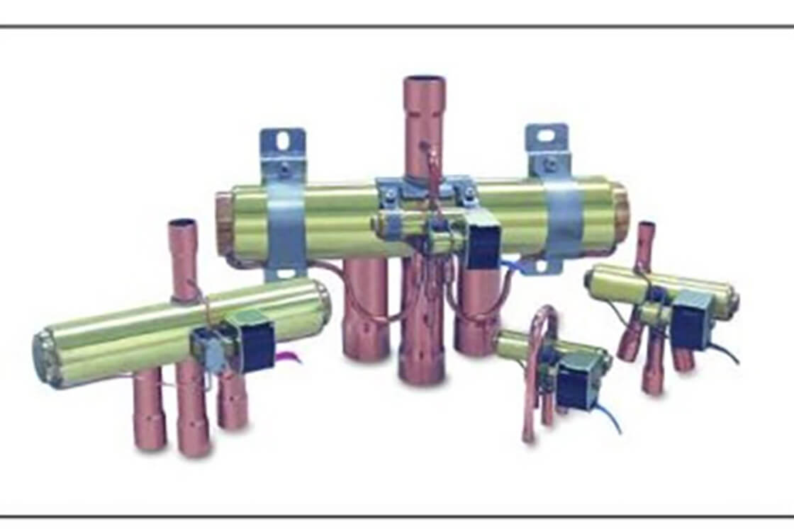
A four-way reversing valve has four pipe connections, three of them on one side and the fourth on the opposite side, whereby the three copper connectors have a larger diameter than the one on the opposite side. The middle one of the three large-diameter connectors is permanently on the suction side, and the single small-diameter connector is permanently on the high pressure side. Since the remaining two may be on either the suction or the high pressure side – depending on how the unit is currently switched – they are made the same size as the permanent suction connection in order to take account of pressure drops. A four-way valve also possesses a solenoid pilot valve with a coil that can be powered to change the direction of flow of the refrigerant. There are small pilot connections between the small-diameter valve connection and the solenoid pilot valve and from there to the central large-diameter connector.
For the following description we shall suppose that the small (high pressure) connection is pointing upwards, the three other connections are pointing downwards, and the small solenoid pilot valve and its coil can be seen at the front of the unit. A standard four-way valve has only two switch positions – there are no intermediate positions. In switch position 1 there is no voltage on the coil of the solenoid pilot valve. In this position, highly pressurized hot gas from the pilot line of the narrower connector enters the chamber containing the sliding mechanism from the right. At the same time the pressure at the left-hand side of the slider chamber can be relieved via the permanent suction connection, discharging the gas to the low pressure side. This displaces the slider towards the left and opens the main paths at the top, leading down to the right and from left to the center. In switch position 2 the hot gas makes its way from the top towards the left, while suction gas is simultaneously allowed to flow downwards from the right into the center. This is achieved by applying mains voltage to activate the coil of the solenoid pilot valve so that high pressure gas is introduced into the slider chamber from the left. This allows the pressure on the right to be relieved via the central main connection at the bottom, causing the slider to move to the right.
Application
Four-way valves are used to reverse the cycle of one-to-one heat pumps. This makes the evaporator into a condenser and the condenser into an evaporator. This possibility is also very welcome for air-to-air heat pumps that are used in summer for cooling and in transitional periods for heating. While the four-way valve will hardly be needed in summer, while the system is in cooling mode, in winter it may be necessary to reverse the cycle in order to defrost the system. Four-way valves offer an extremely efficient way of defrosting both air-to-air and air-to-water heat pumps. Reversing the cycle of a one-to-one system enables the evaporator, which has become a condenser, to be defrosted from inside. This means that there is no need for heat to be applied to the evaporator package by providing an electric heater, instead the hot gas is directed through the pipes that have become iced up. This defrosts the system extremely well and can scarcely be beaten for speed, energy consumption and targeted heating.
Conclusion
Four-way valves are components that offer an extremely efficient way of defrosting air-to-air and air-to-water heat pumps. Complete reversal of the cycle makes it possible to also use the system for cooling. The design is not at all complicated and follows from the dimensions of the suction line, with no need to worry about minimum pressure drops.