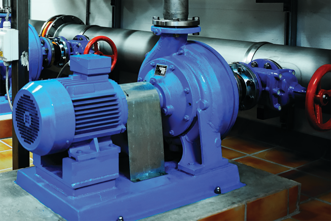
When developing booster pump controllers, the focus is often on the control of the pumps, which is of course the main function of the system. Service and maintenance are not always taken into consideration. As a result, it is often difficult to maintain partial operation of the system when there is a pump malfunction.
When designing the controller for a booster set, it is also important to think about how maintenance and repair issues can best be handled. It is very important to have a standard procedure in place to take any pump in the system out of operation, including the lead pump. Thereby the controller should always maintain “normal” operation, even if the lead pump is taken out of operation.
This video shows an example of how a booster pump system is set up using the Danfoss frequency drive VLT® AQUA Drive and the built-in optional extended cascade controller. With this setup the operator is able to activate an interlock on any pump in the system and if that happens to be the lead pump, the built-in cascade controller will simply set a different pump as lead pump. When the interlocked pump is back online, the drive takes it into consideration again but does not change the lead pump.
If necessary the entire booster set can be put in interlock, disabling any remote start signal and securing that no contactors are activated during service. Here is an example of how booster pump control is set up in the VLT® Motion Control Tool MCT 10 software.
