Commercial Refrigeration
Additional Schrader port for Optyma™ A1 & A2L/A1 packaged Slim Pack W05 ranges
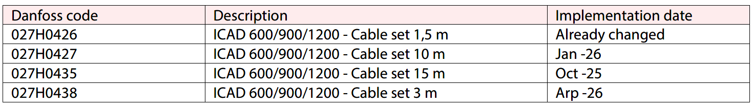
As part of our ongoing product upgrades to the Optyma™ Slim Pack A1 and A2L/A1 ranges W05, Danfoss has modified the liquid line piping and added a Schrader port. This allows the unit to be equipped with accessories such as the Danfoss XGE-EC fan speed controller (Danfoss code 061H3246) for A2/LA1 B3 chassis unit equipped with EC fans, or Danfoss XGE-2CIQ01 fan speed controller (Danfoss code 061H3148) for A1 B1 and B2 chassis equipped with AC fans.
Service valve with braze type connection
B1 chassis
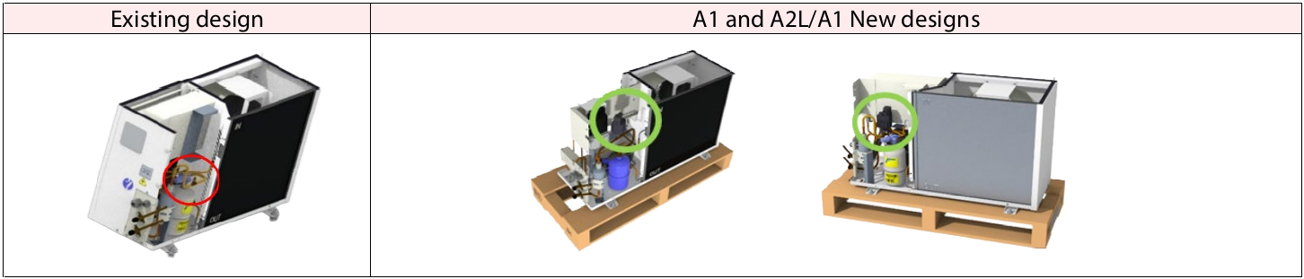
B2 chassis
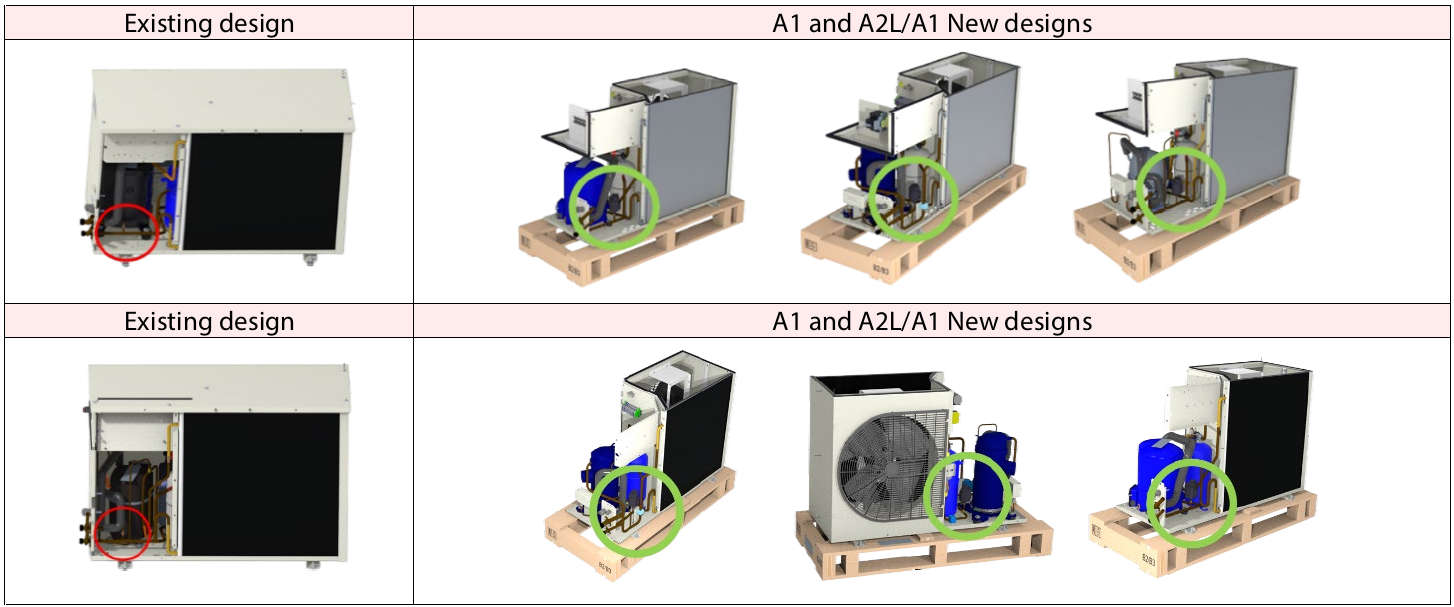
B3 chassis
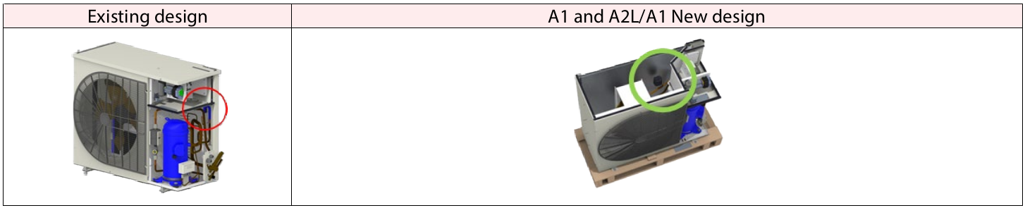
For existing field replacement, customers need to adjust the tubes for suction and liquid lines with the extended service valves.
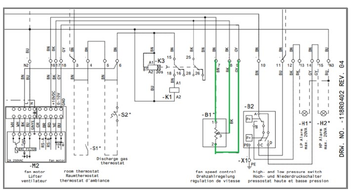
For modified products fan speed controller can be added directly before or after commissioning with Schrader valve support. Electrical wiring should follow stat of the art and the wiring diagram from our instruction manuals:
- A1 units: AN40143613378401-010302.pdf
- A2L/A1 units: AN37261865152502-010602.pdf
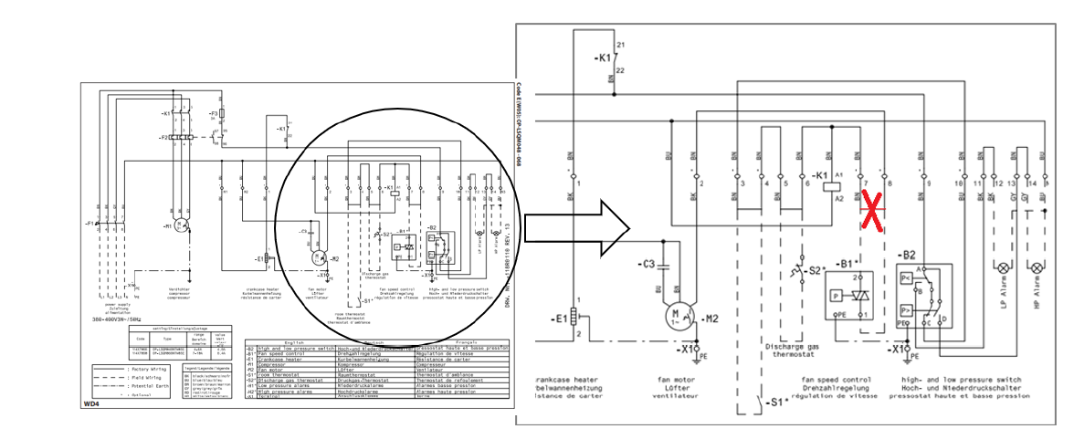
Following the wiring diagrams you can experience 2 cases (example for single phase unit):
1. For B1, B2 and B3 chassis, AC fans XGE-2CIQ01 controller, Danfoss code 061H3148
• Remove the bridge 7 to 8 and Connect 2 to 7 and 1 to 8
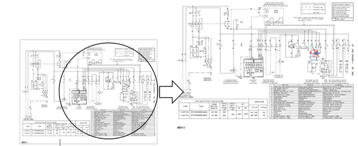
 2. For B3 chassis, EC fans XGE-2CIQ01 controller, Danfoss code 061H3248
• Remove connection between 7 and 9 and R3 potentiometer connection R3
Implementation is already done, serial number on week 24 28 and 31 2023:
B1 panels, Serial number: 179790CG3123,
B2 panels, serial number: 179243CG2823,
B3 panels, serial number: 178973CG2423.
Update - MTZ 4-cyl compressors qualified with R454A/C and R455A
We are pleased to announce the addition of the MTZ160 motor code 3 model to our A2L qualification program and its implementation into production.
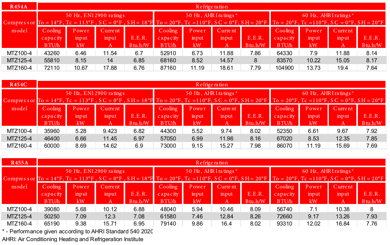
The MTZ models listed below are qualified for use with refrigerants R454A/C and R455A, classified in Refrigerant Group 1. R454A has a GWP of 238, while R454C and R455A have a GWP below 150. These refrigerants are classified as A2L, indicating low flammability properties. Please refer to European regulations (EN378, EN60335) and EPA rulings in the US for safe use. Outside of Europe and the USA, consult local regulations.
The following compressor models are qualified for use with R454A/C and R455A:
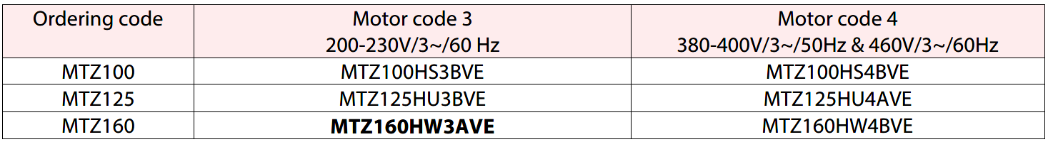
All compressor models, except the MTZ160 motor code 3, are qualified with R454A/C and R455A starting from July 2025. The MTZ160 motor code 3 is approved starting September 2025, with the first serial number following the change implementation being 1009521266.
R454A/C and R455A are zeotropic refrigerants with a temperature glide of about 6 to 12K and must be charged in the liquid phase. Despite the MTZ and NTZ compressors being loaded with 175PZ, R454A/C and R455A can significantly dilute the oil. To prevent lubrication issues, a crankcase heater must be used. This heater protects against off-cycle refrigerant migration and is effective if the oil temperature is maintained 8–10K above the saturated low-pressure temperature of the refrigerant. Tests should be conducted to ensure the appropriate oil temperature is maintained under all ambient conditions.
A PTC crankcase heater is recommended for all stand-alone compressors and split systems, as they are self-regulating. In extreme conditions, such as very low ambient temperatures, a belt-type crankcase heater may be used in addition to the PTC heater. The belt crankcase heater should be positioned on the compressor shell as close as possible to the oil sump for optimal heat transfer.
There is no change in the ordering process; compressor codes remain the same. Compressor nameplates for Refrigerant Group 1 will be adopted accordingly, as informed in FRCC.EN.431.A1.02 (Compressor nameplate: Group 1 and 2, PED MTZ/NTZ One Cylinder Models). Compressors are also marked with a flammable refrigerant logo. For more information, please refer to the CoolSelector2 selection program available at www.danfoss.com.
Nominal performance data:
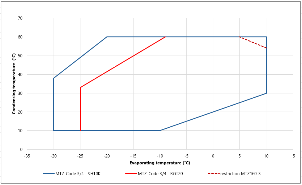
Please follow the operating map presented below.
Climate Solutions – BOCK®: Digital provision of assembly instructions
Summary
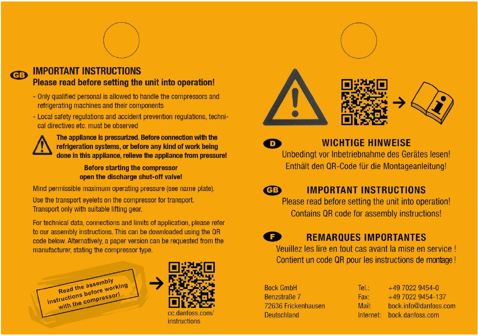
As part of our commitment to environmental sustainability and enhanced customer service, Danfoss is transitioning to a digital format for assembly instructions for BOCK® compressors. Printed instructions will no longer be included in compressor packaging. Instead, comprehensive instructions will be readily available on the Danfoss website.
If needed, instructions in paper format can be requested with delivery within one month.
The digital instructions are accessible via a QR code found on the compressor tag or via the website URL cc.danfoss.com/instructions for easy access.
Compressor tag with QR code:
Description
In alignment with our eco-conscious initiatives, Danfoss will be dematerializing printed instructions within compressor packaging. This transition does not only reduce paper consumption but also provides customers with the most up-to-date information regarding product evolutions, including new refrigerant qualifications and expanded performance maps.
Detailed instructions can be accessed at the following URL: cc.danfoss.com/instructions.
Affected products
This change affects all BOCK® products, except for ATEX and UL compressors.
Customer impact
The transition to digital instructions will not affect the compressor's functionality, performance or safety in any way. This change solely pertains to the method of accessing product instructions.
Verifications
The transition complies with European Regulation on Machinery (EU) 2023/1230 (replaces Directive 2006/42/EC) for incomplete machinery, defining mandatory health and safety requirements that machinery products must fulfil. Article 10 paragraph 7 thereof permits the sole digital publication of operating instructions, if they are easily accessible in the long term via barcode or URL on product or packaging, and are available in paper form on request.
Implementation
The change will take place on 1st December and will be gradually implemented. The change does not affect compressor parts numbers. Implementation is only valid for compressor which are produced in Germany and Czech Republic.
Online Support
You can access and download detailed product information from Product Data Tool in the Partner Portal: Partner Portal/Product Data Tool 
Food Retail
Industrial Refrigeration
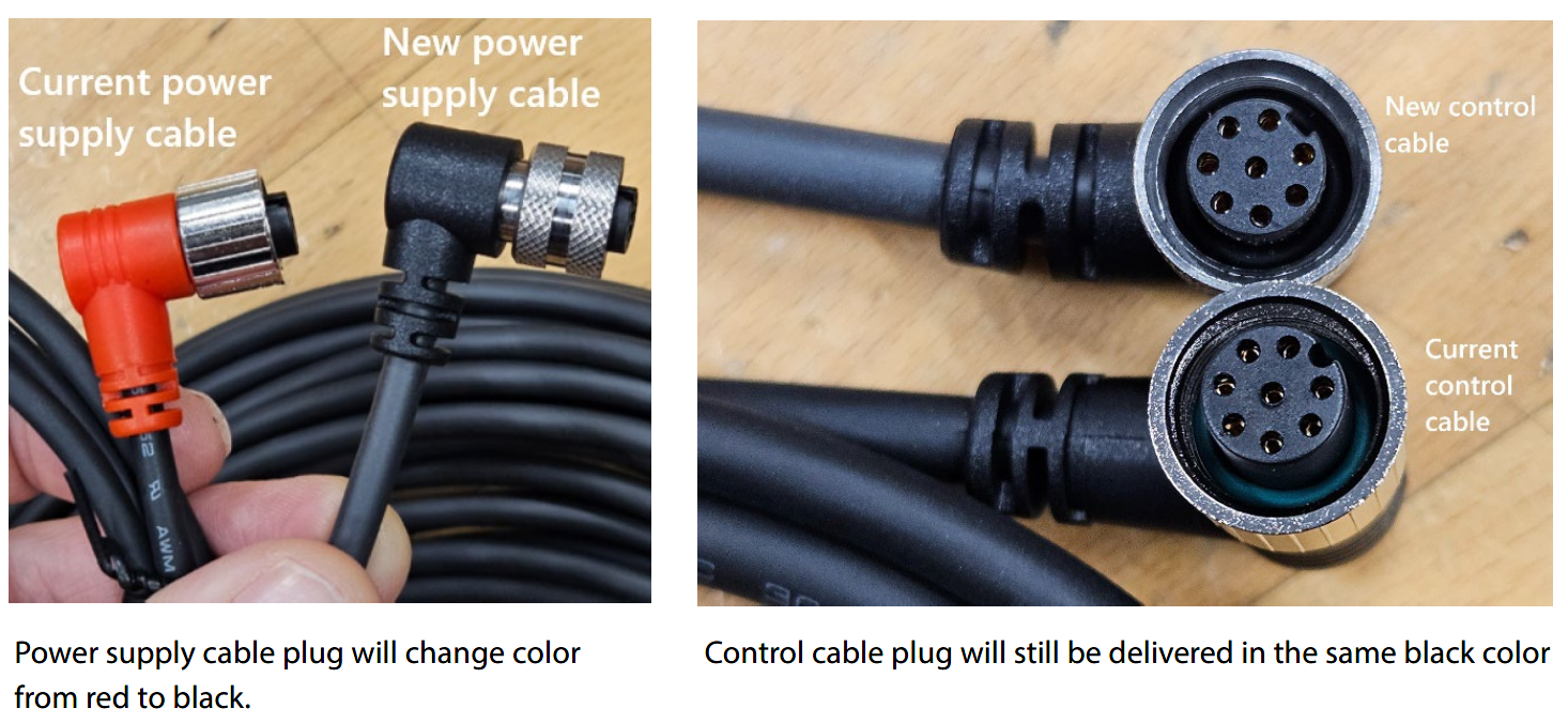
New 2x cables for ICAD actuators
2x cables which were introduced for ICAD A but now only used for ICAD B (power supply cable and control cable). Going forward these will be delivered to an improved quality with better UV resistance and stainless-steel connections. These improved cables are already used in 3x cable sets for ICAD B actuators.
Code numbers affected:

Timing