This is what happened at Lucerne Cantonal Hospital: the demand for refrigeration capacity became higher and higher as the years went by. The hospital’s technical services department repeatedly adjusted the refrigeration plant to cope with new requirements, even expanding the existing pipe network – for example, by increasing the capacity of the main connections (three-line principle). For two of the consumers (Sterilog and Eye Clinic), additional pumps were used to secure the consumers’ supply.
Hydraulic balancing of the distribution system was to be achieved using manual control valves or dampers – it was later discovered that the major part of the control technology was not properly adjusted.
Finally, in summer, when outdoor temperatures rose to more than 26°C and a number of consumers complained of discomfort, the need for action became urgent.
Details about Lucern Cantonal Hospital Lucerne Cantonal Hospital (LUKS) is the largest non-university hospital in Switzerland. Its clinics and institutes offer high-quality medical provision – comprehensive diagnostics and a high standard of acute-care medical services around the clock. As they say, “Our patients’ well-being is always our primary concern. And that’s a promise”. There are 5600 employees to look after the patients’ welfare: from a catchment area of 500,000 inhabitants, they see approximately 36,000 inpatients and 148,000 outpatients a year, for whom 900 acute-care beds are available.
LUKS sees itself as an academic teaching hospital and is committed to science-based medicine. Many of the responsible staff at the clinic and institute carry out both clinical and scientific work, and their patients benefit from a national and international exchange of knowledge and skilled staff. LUKS also takes on an extensive rôle as a training centre for most of the professions employed in the public health system – offering no fewer than 1400 fascinating apprenticeships.

The challenge
A convoluted refrigeration network that has evolved over a period of 30 years, whose parameters are largely unknown. What is known: the system is inefficient – and is liable to be unable to provide DCW to all its consumers any time the external temperature rises above 26°C. Another known fact is its high power consumption.
There are four pumps installed to distribute DCW from the refrigeration unit. The smallest of these is used in winter. The three larger pumps are added and their speeds regulated during the summer in response to demand. Distribution of the refrigeration capacity is divided into four main outlets from the control centre: Ventilation station 1 (house 31); Ventilation station 2 (house 31); Distribution East [last consumer: Children’s Hospital (house 33)]; Distribution West [last consumers: Sterilog (house 16) and Psychiatry (house 11)].
The approach
Lucerne Cantonal Hospital commissioned the consultant engineers Wirthensohn AG to analyze the situation. The engineers’ starting point was by no means straightforward: there was no schematic overview of the refrigeration distribution indicating its capacity, and there was only one site overview showing the pipe layout. For this reason, Wirthensohn first drew up a schematic of the distribution for the entire site on the basis of existing documents, and then also determined the needs of all the consumers.
The results of this analysis: A total refrigeration capacity of 4700 kW (two adsorber refrigeration units plus a turbocharger) is faced with a 100% refrigeration demand of 6900 kW. It follows that the existing capacity can provide the required level of refrigeration with up to 70% simultaneity – based on an assumed outdoor temperature of 30°C.
Wirthensohn’s engineers therefore concluded that the existing system should be sufficient for its current consumers on all but few days each year. However, this is conditional on water from the refrigeration system being distributed optimally – which is not guaranteed. The main problem, they decided, was the lack of hydraulic balancing over the entire refrigeration distribution system. This cannot be provided using the existing static control technology.
Wirthensohn therefore recommended implementing state-of-the-art hydraulic balancing – with the proviso that only dynamic hydraulic balancing could guarantee optimum water distribution.
Danfoss engineers then analyzed the refrigeration capacity in collaboration with Wirthensohn, and specified the positions and the performance of the necessary controllers.
The solution: dynamic hydraulic balancing
What is hydraulic balancing – and why is it so extraordinarily important?
Water flows through a supply network (whether heating or cooling) according to the principle of least resistance. If there is no hydraulic balancing, the consumers nearest to the refrigeration unit will be favored, more remotely installed consumers will be at a disadvantage due to the greater pipe resistance.
Hydraulic balancing distributes the water evenly throughout the network:
- All consumers receive the correct amount of water, and hence also the required capacity
- The temperature differentials across the consumers will then be correct, and therefore so also will be the return temperatures
- If the returning water has the ‘right’ temperature, the refrigeration system will be functioning optimally and achieve its maximum performance
- The fact that only water that is actually needed flows to the consumer reduces the power needed for pumping
- Hydraulic balancing calls for specific additional water resistors to be installed. These may be static or dynamic control devices. What’s the difference?
Manual controllers:
Manual control devices include dampers, valves, etc. Such fittings can be used to adjust a fixed resistor, the adjustment being determined from a precise pressure loss calculation. The downside: if the system is extended then all valve settings will need to be recalculated and set up afresh.
Self-acting controllers:
- These respond dynamically to changing pressure conditions in the system. Their resistance is regulated by measuring the pressure and using it (with a spring as auxiliary energy source) to adjust the built-in regulating valve. The force exerted by the spring is adjusted according to the desired volume of water and the pressure required at the specific connection. Determining this force requires only that both the desired design volume of water and the pressure loss between the valve installation point and the consumer are known.
- The pump pressure is dynamically held constant within the consumer network (with static control devices, the pump pressure is correct only for the maximum volume of water). The consumers’ motorized regulating valves then behave optimally, even during partial load operation
- The system can immediately respond to pressure changes within the system (e.g. when a neighboring consumer is switched in or out)
- When the system is extended there is no need to readjust the valves
- The maximum flow rate of the outlet can be adjusted so that no consumers are favored
- The settings are easier to determine
In addition, using differential pressure controls reduces the flow rate at partial load, which in turn reduces the pump’s energy consumption. Optimizing partial load operation also improves the system’s Δt behavior (constant ratio between supply and return temperatures), which has a favorable effect on the chiller’s coefficient of performance (COP).
The result
Data pertaining to the current system were recorded in the summer of 2010. On the basis of that data sheet, 33 Danfoss AFP VFG2 controllers of nominal diameters DN 25 to DN 150 were installed. Hydraulic balancing was carried out in the winter of 2011/2012, and could then be verified by measurements taken during the summer of 2012. Comparing the before/after data showed that it was possible to save 20% of energy costs using the installed refrigeration equipment!
The cost of renovating the hydraulic network will be amortized in a few years by this marked reduction in operating costs.
Lucerne Cantonal Hospital’s technical services department informs us that in 2012, for the first time, no shortfalls were encountered at external temperatures higher than 26°C. 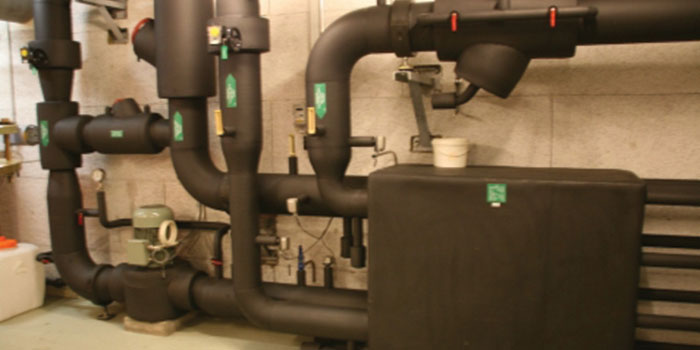
Overview of the installation
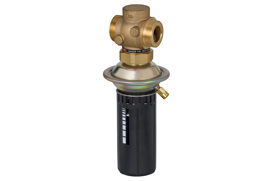
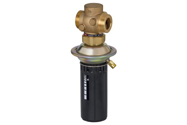
33 Danfoss AFP VFG2 controllers of nominal diameters DN25-150 were installed.
The AFP VFG2 controller is a direct-acting proportional control valve that controls differential pressure and has no need of an external power supply.
The self-acting control valve is normally open, closing as the differential pressure rises.
It consists of a balanced regulating valve (flanged connection) plus an actuator with a reinforced diaphragm and a set-point spring for adjusting the differential pressure set-point.
Related products
-
if (isSmallPicture) {

Differential pressure controllers keep a constant and lower differential pressure across a motorized control valve or a total system/substation. This eliminates pressure variations and improves temperature control quality.

Modern medical technology and IT centers need to have a great deal of refrigeration capacity available around the clock.
As more and more consumers were connected to Lucerne Cantonal Hospital’s refrigeration systems, the existing capacity was sometimes, in summer, found to be no longer sufficient everywhere, and it was decided to install more powerful chillers.
But surprisingly, the planner who was commissioned to carry out the relevant analysis reached a different conclusion: a better and far more cost-effective solution would be to install self-acting controls for hydraulic balancing in the existing refrigeration network.