What is an ejector, and how does it work?
An ejector is a device that utilizes the energy from the high-pressure work. The ejector converts the high-pressure potential energy in the motive flow (primary) into kinetic energy, drawing a flow from the suction port (secondary flow).
The process, shown in Fig. 1, is driven by the high-pressure CO2 gas leaving the gas cooler. The gas enters the ejector at the high-pressure port (PH) and flows through the throat which causes the flow to accelerate. At the exit of the ejector nozzle, the gas is at supersonic speed, creating a low pressure (PS). As low pressure (PS) is lower than the pressure (PL) at the suction (secondary) nozzle, CO2 is flowing from the suction port into the ejector.
The two flows are mixed in the mixing chamber and the pressure is gradually increased. The flow finally enters the diffuser at the end of the ejector. Because of the conic diffuser shape, the flow gradually slows down, and the pressure is increased. This means that the kinetic energy of the flow (velocity) is converted to potential energy (pressure). After leaving the diffuser, the gas is at a higher pressure (PD) than the suction pressure (PL).
Danfoss ejector design
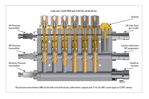
All ejectors in the Danfoss portfolio have a high-pressure inlet (high-pressure CO2 gas from the gas cooler), a suction inlet (from MT evaporators or suction accumulator), and an outlet for returning the gas or liquid to the receiver. The coils activating the individual ejectors are available from 110 to 230 V, 50 and 60 Hz. The Multi Ejector HP and LP ejectors is delivered with three pressure transmitters, used for pressure control in the AK-PC 782A pack controller. The Multi Ejector is available in different versions, depending on the application. Each block has a variable number of ejectors of different sizes mounted vertically.
Multi Ejectors HP and LP are available with 4 to 6 ejectors, while the Liquid Ejector has 1 or 2. The capacity requirement
is matched by using different numbers and combinations of ejectors. The characteristics of the ejectors remain the same no
matter how many ejectors are in use. On each individual ejector, a built-in non-return valve prevents backflow, removing the need for external check valves in suction lines.
Capacity control
Ejector capacity control is achieved through a binary coupling of various capacities. The Multi Ejector HP, for example, comes in two versions. The 4-ejector version has ejectors providing 6 kW, 12 kW, 25 kW, and 50 kW. Resulting in a total of 93 kW refrigeration capacity. The 6-ejector version has two additional 50 kW ejectors, providing a total of 193 kW of refrigeration capacity. This makes it possible to modulate capacity in 32 steps between 0 and 193 kW in 6 kW steps. If more capacity is required, a second Multi Ejector HP can be added, and controlled in parallel. Similar at the Multi Ejector LP control the capacity in 3 kW steps and the maximum capacity that can be served is 43 kW for 4-ejector version and 93 kW for the 6-ejector version. The Liquid Ejector LE 600, is controlled in the same way, just with 4 steps.
User-friendly features and easy maintenance
The Multi Ejector SolutionTM offers several features that make commissioning, operation, service, and troubleshooting easier. Each individual ejector can be fitted with an optionally LED DIN plug which indicates whether the coil is activated or not; a very useful feature during commissioning or troubleshooting. All Multi Ejectors come with a strainer mounted on the HP inlet before the individual ejectors, eliminating the need for external filters. Each individual ejector and the strainer are easily serviced by simply removing the four mounting screws, using a screwdriver to lift the ejector or strainer, and pulling it out of the block. The strainer can easily be taken apart for cleaning or replacement.
Multi Ejector Low Pressure: optimizing booster system energy consumption
The Multi Ejector LP (Low Pressure) is designed for CO2 booster systems. Depending on ambient temperatures the LP ejector has different functions. In warm ambient conditions, the ejectors can lift all the gas from the evaporators into the receiver. The level of the pressure lift the ejector can achieve is also dependent on the ambient conditions. The higher the temperature the higher the pressure lift that can be reached. The compressors are therefore compressing the gas from the receiver, which is at a higher suction pressure than the evaporator and this is lowering the system energy consumption.
The ejectors can assist the compressor when ambient temperatures are above 20 degrees. The higher the ambient
temperature the larger the contribution to the energy-saving can be achieved. Therefore, the overall energy efficiency and saving are dependent on the number of hours per year the temperature is higher than 20° C and the temperature profile.
In cold ambient conditions, the LP ejector serves the same functions as a conventional high-pressure valve controlling the
system to perform at optimum COP. As an example, Low-Pressure ejectors can increase the suction pressure of the compressor by 3 bar (known as pressure lift) at 23° C providing a 63% entrainment ratio. While at 36° C, the lift is 7 bar the entrainment ratio is 50%. Ambient temperature is a very important parameter for the calculation of the improvement and energy saving the ejector solution can provide.
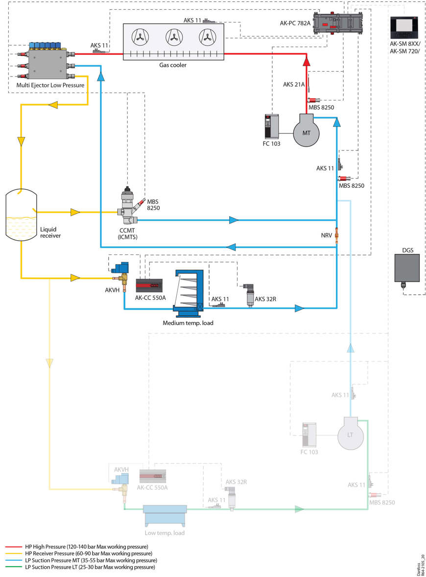
A system with Multi Ejector LP will provide more benefits in a location where the temperature is above 20°C for a substantial time. As an example, taking the average weather in Athens the run time of ejector is 71% (temperatures over 20°C), while for Copenhagen the run time is 25%, hence the saving due to ejectors will be higher in Athens than in Copenhagen. The Multi Ejector LP is well suited to warm climates and stores with a cooling capacity between 40 and 150 kW.
| Low Pressure (LP) | |
| Ambient temperature | Warm |
| CO2 system | Booster |
| Optimal system size | 40-150 kW |
| Media on the suction side | Primarily gas |
| Lift/entrainment – @low ambient | 3 bar/63% @ 23°C |
| Lift/entrainment – @high ambient | 7 bar/50% @ 36°C |
Benefits of the Multi Ejector Low Pressure
- Energy consumption can be lowered by up to 15% compared to a booster system*.
- System costs are reduced, as there is only one suction group.
- Required capacity can be reduced and potentially result in the use of smaller compressors.
Multi Ejector High Pressure: optimizing parallel compression systems
The Multi Ejector HP (High Pressure) relies on the same basic Multi Ejector principle but is designed for parallel compression systems. In warm ambient conditions, the High-Pressure ejector lifts some of the gas from the evaporators to the receiver. From the receiver, the gas is compressed directly by the parallel (IT) compressor. When ejectors are operating, part of the MT load is moved to the parallel (IT) compressor. Hence, this reduces the load on the MT compressors in the system, as the load is moved to the parallel (IT) compressor. The parallel compressors operate at a higher suction pressure, resulting in lower energy consumption. In cold ambient conditions, the HP ejector serves the same functions as a conventional high-pressure valve controlling the system at the COP optimum.
The Multi Ejector HP can achieve a higher pressure lift than the Multi Ejector LP but at lower entrainment ratios. Like the Multi Ejector LP, the Multi Ejector HP is well suited for warm climates and it requires ambient temperatures of above 20° C to increase system efficiency.
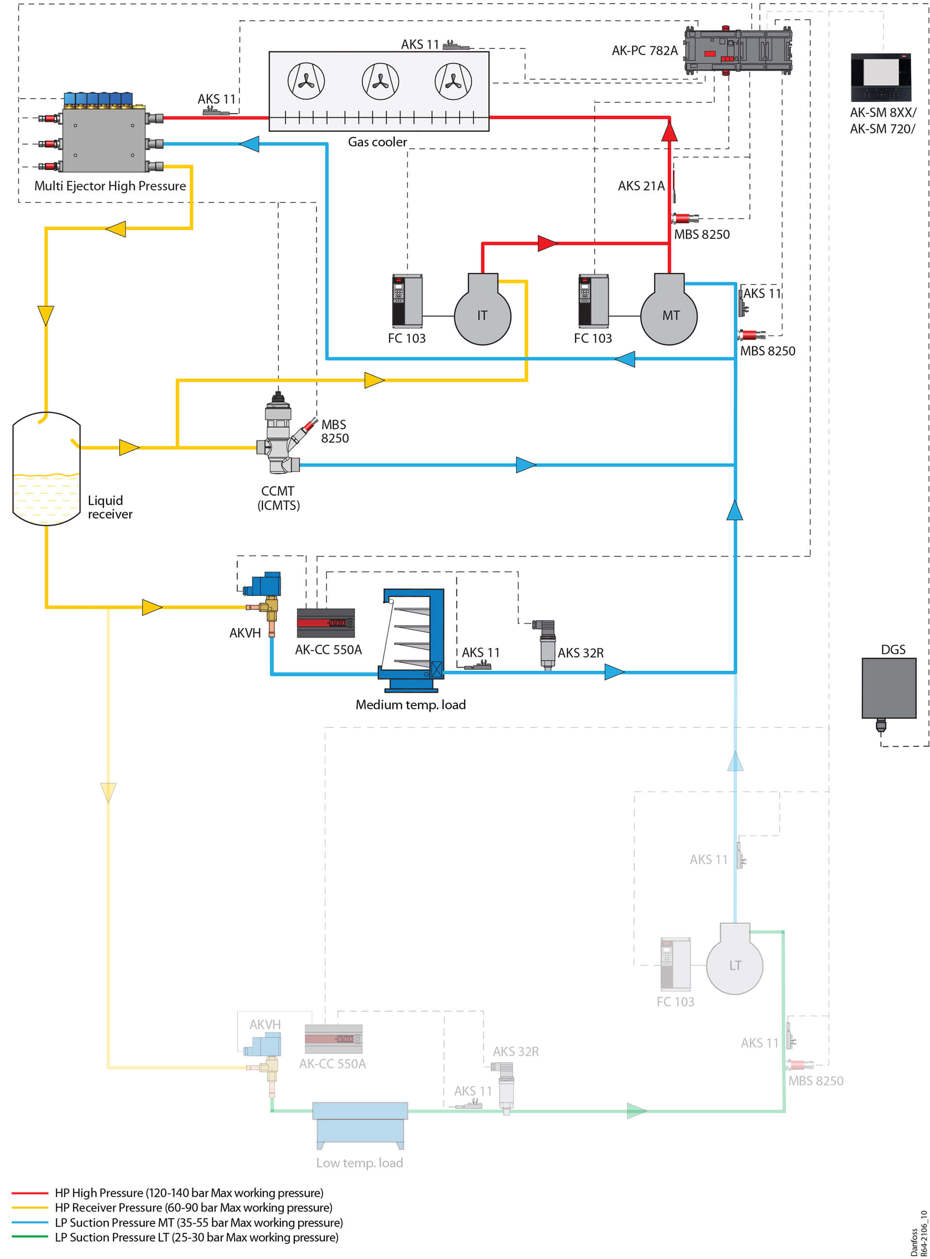
High-Pressure ejectors can increase the pressure by 6 bar (known as lift) at 23° C providing an entrainment ratio of 25%. At 36° C, the lift can be 11 bar providing the same entrainment ratio of 25%. Higher pressure lift can be supported in higher temperatures providing the same cooling capacity.
The pack controller is supporting variable receiver pressure, to ensure optimal performance of the ejectors in all conditions.
Ambient temperature is a very important consideration when selecting ejectors. The higher the ambient temperature the more the benefits. The factors that control the energy saving is the temperature profile throughout the year, The Multi Ejector HP is well suited to warm climates and stores with a cooling capacity between 100 and 300 kW.
| High Pressure (HP) | |
| Ambient temperature | Warm |
| CO2 system | Parallel compression |
| Optimal system size | 100-300 kW |
| Media on the suction side | Primarily gas |
| Lift/entrainment – @low ambient | 6 bar/25% @ 23°C |
| Lift/entrainment – @high ambient | 11 bar/25% @ 36°C |
Benefits of the Multi Ejector HP
- Energy consumption reductions up to 9% annually in warm climates compared to parallel compression, and by up to 17% compared to booster systems*.
- System costs may be reduced because of the number or capacity of the compressors can be reduced, depending on the system architecture.
Liquid Ejector: optimal evaporator utilization and efficient compressor protection
The Liquid Ejector is designed for both booster and parallel compression systems. The working principle in the Liquid Ejector
is similar to the gas ejector. The Liquid Ejector is optimized to lift liquid from the suction accumulator, returning it to the receiver. In a Liquid Ejector system, the evaporators operate with a very low superheat and a fraction of liquid is returned to the suction accumulator, located downstream of the evaporators. With the support of an appropriate & intelligent case controller with Adaptive Liquid Control (ALC) algorithm, the evaporator functions more efficiently at a higher suction pressure. This enables the suction pressure to be raised, thereby reducing the energy consumption on the compressors.
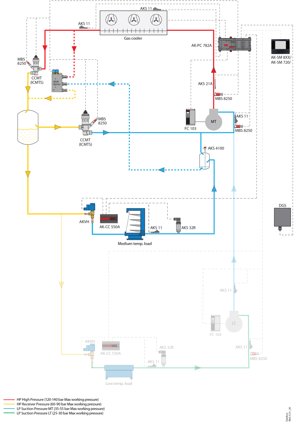
The key to achieving the performance benefits enabled by the Liquid Ejector is the use of the Adaptive Liquid Control (ALC)
algorithm available in the newest generation of Danfoss case controllers. This algorithm makes full use of the entire surface of the evaporator, maximizing its efficiency and operating with the lowest possible superheat (close to 0K). The ALC algorithm can control the liquid volume in the evaporators very precisely so that only approximately 3% of the refrigerant volume remains liquid. This means that the size of the suction accumulator is minimized. Since the Liquid Ejector is powered by the work which would have been otherwise lost, there is no additional energy used to accomplish this.
For more information on the ALC evaporator control algorithm, please see our article Selecting the right evaporator injection
algorithm makes a world of difference.
The Liquid Ejector is capable of increasing the pressure by 5 bar (known as lift) providing 17% entrainment ratio at 5° C ambient temperature, while entrainment ratio is increased to 35% at 20° C. The Liquid Ejector is able to pump the accumulated liquid to the receiver under all ambient conditions. The Liquid Ejector is well suited to all climates and stores with a cooling capacity between 40 and 300 kW.
| Liquid Ejector (LE) | |
| Ambient temperature | Warm and cold |
| CO2 system | All transcritical CO2 systems. |
| Optimal system size | 40-300 kW |
| Media on the suction side | Primarily liquid |
| Lift/entrainment – @low ambient | 5 bar/17% @ 5°C |
| Lift/entrainment – @high ambient | 8 bar/80% @ 36°C |
Benefits of the Liquid Ejector
- Energy consumption can be lowered by 2-12% annually in any climate compared to regular booster systems*.
- Reduced system complexity, shorter payback time, and improved reliability.
- As the Liquid Ejector is designed to lift liquid at low pressures, it can work at lower operating pressures and is, therefore, efficient in any climate.
What are the entrainment ratio and pressure lift?
The mass entrainment ratio Φ of the ejector is defined as the ratio of secondary mass flow (suction flow) over the mass flow of the primary flow (motive flow), and it measures the ability of the ejector driving the flow from the evaporator.
Φm = msn / mmn
The pressure lift is a performance characteristic determined by the design of the ejector, the operational conditions and system control. It is defined as the difference between the pressure at the p outlet of the diffuser and the pressure at the inlet of the suction (secondary) port. In the system that the parameter defines the difference between the receiver pressure (Pdiff, out) and evaporator suction pressure (Psn, in).
Plift = Pdiff,out – Psn,in
The work potential recovered from the primary flow of the ejector can be applied between two extremes; A) achieve
a large lift of a small amount of secondary flow, or B) give a large amount of secondary flow a small pressure lift.
Significant energy savings possible
A German supermarket installed Multi Ejector High Pressure and Liquid Ejectors in a transcritical CO2 refrigeration system with parallel compression. The system has three suctions groups with a load of 230 kW MT, 85 kW LT, and 125 kW (IT). The use of parallel compression, ejectors, and the ALC algorithm resulted in a 28% reduction of energy consumption compared to systems built in 2017 and registered in the German VDMA-Effizienz-Quickcheck database. This energy reduction resulted in annual savings of EUR 61,000. (Note that the open source database is continuously updated with new installations and that the basis for comparison will, therefore, be continuously updated, providing different results over time.)
CO2 Adaptive Liquid Management
The Danfoss solution for managing liquid in transcritical CO2 refrigeration applications is based on enhanced versions of case controls, pack controls and system managers, together with the Liquid Ejector. This solution is called CO2 Adaptive Liquid Management (CALM) and it represents a major step forward in refrigerant management. CALM ensures integration between the case controls, pack controls and system managers enabling a safe operation in Liquid Ejector systems in all conditions.
Conclusion
Exploiting the physical properties of the refrigerant and system design, Danfoss Multi Ejector Solution™ is key to ensuring high energy efficiency in transcritical CO2 refrigeration systems. For booster systems, compressor load can be reduced with the Multi Ejector LP. For parallel compression system, the Multi Ejector HP can enhance the IT load, while the MT load is reduced. The Liquid Ejector can improve the energy efficiency of any CO2 refrigeration solution by enabling optimal evaporator utilization. With the Multi Ejector Solution™, Danfoss offers significantly improved efficiency in any CO2 refrigeration application, in any climate, making CO2 the most efficient refrigerant.
For more information, please contact your local Danfoss sales office, or visit multiejectorsolution.danfoss.com