Thermostatic expansion valves are standard use in commercial refrigeration plant construction, and are therefore widely-used in compression refrigeration systems with dry expansion. They are used for optimum evaporator admission flow, and with varying load conditions. Some points in particular must be observed with their dimensioning, which will now be more precisely illuminated in this article.
Function
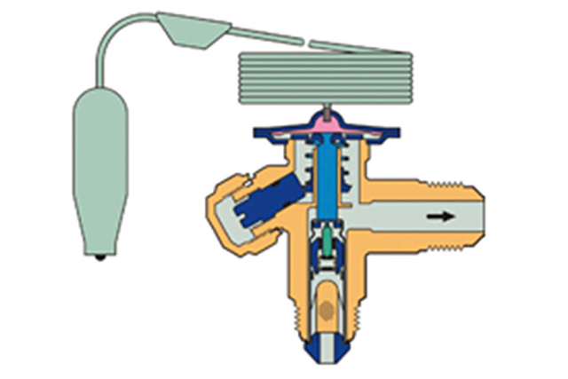
Thermostatic expansion valves ensure that sufficient superheat is always guaranteed at the evaporator outlet, so that the compressor constantly aspires refrigerant vapor without being damaged. The superheat is the difference between the measured temperature value on the evaporator output and the saturated vapor temperature of the pressure read out from the manometer. At the same time the entire exchange surface of the evaporator is also used. This means it needs no electrical connection or higher externally supplied pressure to function. The thermostatic expansion valve consists of a thermostatic element with sensor, a sensor charge, a diaphragm, a tappet connection between the diaphragm and valve seat and a housing. Liquid refrigerant from the liquid line – coming from the receiver – is present at the expansion valve. This liquid is now controlled by the expansion valve and injected via the injection line and (if required) a refrigerant distributor into the evaporator. The sensor is attached to the evaporator output and care must be taken to ensure the evaporation pressure under the diaphragm in the expansion valve is always present.
The first step to select and dimension the right thermostatic expansion valve is to choose the refrigerant. There are a very wide variety of expansion valves. This is because a different expansion valve is used for practically every refrigerant, the reason being the sensor charge of the expansion valve, which must be harmonized with the temperatures and pressures of the specific refrigerant. R507 and R404A are exceptions here. The pressure-temperature properties of these two refrigerants are so similar that the same valve series can be used. Operation is also possible with the R407C refrigerant with R22 expansion valves with adjustable superheat. Only the superheat must be adjusted accordingly for this. With refrigerants whose pressure-temperature curves differ significantly from one another – such as with R134a and R404A for example – the expansion valve that is specifically intended for the refrigerant used should always be chosen in every instance. If it is not, the result will be either liquid refrigerant upstream from the compressor or insufficient evaporator admission flow.
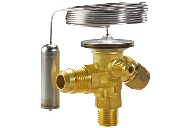
Standard expansion valves with exchangable orifice T(E)2
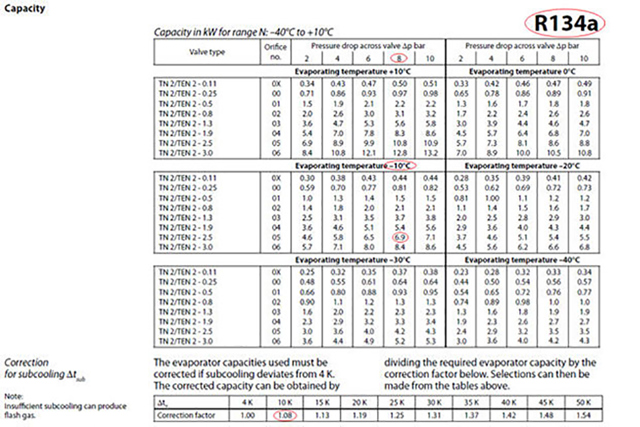
The size of the required expansion valve also varies with different system subcooling values. The subcooling is the condensing temperature minus the liquid temperature upstream from the expansion valve. So with otherwise identical system data, you need a smaller valve with greater subcooling (e.g. 40K) than with 4K, for example. This follows from the information that is usually available for the dimensioning. The pressure drop of a valve essentially depends on the volume flow. This information is, however, not normally stated in the commercial refrigeration industry. In practice, only cooling capacity, refrigerant and evaporation temperature are available for dimensioning. The subcooling and the condensing temperature are often already the first two assumptions. In practice, it makes no difference whether the subcooling is 4 or 5K, but it does with 4 or 40K. The degree to which an expansion valve can be smaller when the refrigerant is additionally subcooled by 40 K can be seen from the correction factors when dimensioning using datasheets. In cases such as this, the required capacity value of the expansion valve with R134a is reduced by 30% (correction factor 1.42). Different correction factors are applied to other refrigerants. These differences in the valve size can be attributed to the correlation of the cooling capacity with the enthalpy difference and the mass flow, which in turn is composed of the volume flow and density. The mass flow multiplied by the enthalpy difference is the cooling capacity. If the enthalpy difference now increases because of subcooling, the mass flow becomes smaller with the same cooling capacity. As the density remains the same, the volume flow is reduced. This indicates a smaller valve.
Cutaway drawing TE2
The next step is to calculate the pressure differences via the expansion valve. This value is required as soon as you want to determine the respective capacity values of the valve in a dimensioning datasheet for the defined refrigerant in a table for the evaporation temperature. The orifice size will now be determined with the evaporator cooling capacity, which is already corrected by the subcooling. Different columns with different values of pressure drop can be selected. With R134a these are 2, 4, 6, 8 and 10 bar. These values appear high when compared with the dimensioning of valves in suction, liquid or hot gas lines. Pressure drops of 1 bar with the R134a should already be considered high here. The expansion valve has a special position in this respect. It is a regulator, and brings the refrigerant from high pressure back to low pressure level again. This is practically the inversion of the compression process, in which low suction pressure was compressed to high hot gas pressure. The evaporation pressure must therefore be subtracted from the condensation pressure to determine this pressure difference. The result, however, corresponds only roughly to the value that should be selected in the dimensioning table. Pressure drop, e.g. via the distributor (e.g. Venturi distributor) of the evaporator, has not yet been considered. For practical purposes it is sufficient to subtract a flat-rate value of 1 bar. If the exact calculated value cannot be found in the dimensioning sheet you should take the column with the next lowest value. With 6.5 bar, for example, that would be the column with the corrected evaporation capacities at 6 bar. The suitable valve series with the precise orifice size can now be taken from the rows of the dimensioning table.
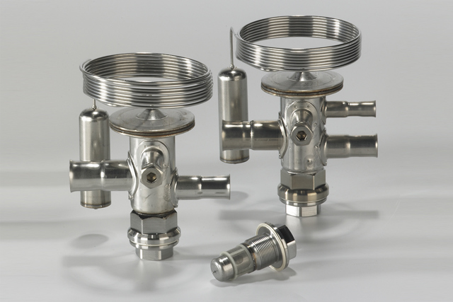
Stainless steel expansion valves with exchangable orifice TUAE
Let us now consider this using a specific refrigeration system. For example, the following typical system is to be given a thermostatic expansion valve: a cold storage room with 7 kW at -10°C evaporation, 45°C condensation and 10 K subcooling, the R134a refrigerant is used. Refrigerant and evaporation temperature are critical for selecting the datasheet. In our case this means: Use of the datasheet for R134a and evaporation temperature range +10 to -40°C. The cooling capacity must first be corrected with the correction factor for subcooling, which can be read in the small table below (see "Dimensioning example" table). At 10K it is 1.08. 7 (kW) divided by 1.08 is 6.5 (kW). As "-10°C" is explicitly identified as its own table, the matching orifice size can be read directly for the cooling capacity 6.5 kW. The pressure drop via the expansion valve is also required, as the condensing temperature is not given directly in the datasheet. The refrigerant slide ruler helps. We can read here that condensing temperature and evaporation temperature are 9.6 bar apart (10.6 bar - 1 bar). To meet the pressure drop via the distributor, we must once again subtract 1 bar from the result. This gives us 8.6 bar. We orientate ourselves on 8 bar Δ p, 6.5 kW cooling capacity, -10°C evaporation temperature and can now look for the right orifice size. The value is 6.9 and the matching orifice size is 5. A "TEN 2" valve ("E" stands for external pressure compensation and "N" for the refrigerant R134a) with orifice 5 for our cold storage room can therefore be selected in this example.
OEM Expansion Valve with Fixed Orifice TGE
If an MOP valve (MOP = maximum operating pressure) is used instead of a standard expansion valve, then it is with the objective of avoiding too high evaporation temperatures. These MOP valves are very popular for deep freeze systems, because deep freeze compressors have a weaker electric motor than normal cooling or air-conditioning compressors, and this protects them against overload. The only technical change with an MOP valve compared to a standard valve is the limited sensor charge. If the complete sensor charge is evaporated at a specific temperature, the sensor pressure increases hardly at all (or only very negligibly). This produces a limit on the upward evaporation pressure. In practice it is important to know that higher superheat can occur in particular with MOP valves, without a malfunction or even a valve that is dimensioned too small.