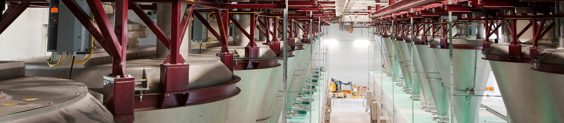
Danfoss drives offer unique integrated condition-based monitoring (CBM) functionality. For installed machines currently with no access to condition monitoring data, these drives provide a convenient way to implement monitoring and begin collecting performance data.
Play video
Along with stator winding monitoring and load envelope, the CBM functionality integrated into the drive includes vibration monitoring. Vibration monitoring is realized with the help of vibration sensors, required for signal collection. The drive supports up to four vibration channels, connected to the analog inputs, 4-20 mA.
Vibration monitoring comprises 2 functions:
The two functions are complementary to each other. The sensors provide a calculated output of a general vibration (v-rms) or bearing condition in wider frequency range (g-rms).
In today's competitive landscape, it’s crucial to make the most of your CAPEX. Invest in a proactive maintenance strategy that goes beyond just the sale. By prioritizing early detection and consistent upkeep, you’re not only safeguarding your investments but also driving long-term savings.
Explore Long-Term Savings Now
In the Danfoss implementation, the vibration is always correlated with motor speed. This is valuable because Danfoss drives offer thresholds adaptable to the state of operation, as opposed to general monitoring using absolute values for the entire speed range. This capability is unique in variable speed operated machines.
The Danfoss vibration monitoring functionality is not a diagnostic system, being able to monitor the change between baseline data and actual values via thresholds. However, the best results in vibration monitoring are always connected with the observation of the change, and a key factor is permanent monitoring of the speed function.
According to the mechanical vibration standard ISO 20816-8:2018, the drive output of the monitoring function must comprise two warnings and one alarm, all selectable. The user receives a notification to acknowledge the status change of the monitored asset and plan maintenance accordingly. This early warning is vital for operators in being able to act fast to prevent unplanned downtime of the application.
In addition to vibration monitoring, the sensors can be useful in determining resonance points from the baseline data, as well as overall machine health, increasing the customer value.
Danfoss has entered a partnership with the global vibration leader, Hansford Sensors (HS). CBM vibration monitoring has been developed, tested, and validated using HS sensors. Hansford is a specialist in vibration theory, sensor selection and placement, and the partnership is mutually beneficial for both companies. Hansford manufactures high quality products with lifetime warranty.
Danfoss offers two types of sensors based on body shape:
There is a difference between optimal placement for v-rms and g-rms sensors.
HS-D20 used for monitoring imbalance, misalignment, and looseness is always on a rigid element of the motor housing. Ideally, position it on the drive end bearing or as close to this as possible. Some motors come prepared with a flat surface. The sensor can be mounted by drilling/threading or with a glue stud or even using a magnet if the surface is magnetic. There is less risk of signal loss for this type of RMS measurement.
Regarding axis, sensors can be mounted vertically or horizontally, as close as possible to the drive end bearing.
One sensor per motor is sufficient for motors rated up to 15 kW. For larger frame designations, we recommend multiple sensors, in a combination of types (v-rms and g-rms).
If only one sensor is installed, it is always good practice to measure both axes and select the one with higher level of vibration for permanent installation. The higher vibration is caused by structural resonance, stiffness, or freedom of movement, and it is important to determine the predominant direction.
HS-D22 measures higher frequencies up to 5 kHz which do not transfer in the motor housing obviously. It measures the condition and lubrication of the bearing on which housing it is mounted. Therefore, mounting on the bearing housing is a must. Quality of the mounting is important for signal consistency. Achieve the best connection by drilling.
For Danfoss drives, connect the sensors to terminal T12 (white) or terminal T13 for 24 V supply and AI53 (black) or AI54 for signal.
VFDs act as intelligent sensors for condition monitoring in automated systems. Explore features of intelligent drives and various maintenance strategies.
Predictive maintenance has emerged as a powerful tool to optimize equipment performance, increase uptime, and reduce maintenance costs.
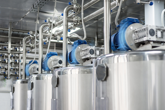
Monitoring motor performance using condition-based monitoring provides a simple and cost-effective way to obtain machine data for smart maintenance decisions.
Remote monitoring empowers users to access real-time data, react early to avoid interruptions, optimize performance, and make informed decisions.