Top ten tech support calls

Below is a list of the most frequent technical support calls received by the Danfoss service department, followed by common solutions for each. Before placing a technical support call, please review this document to see if a solution is listed for the problem you are experiencing. If the problem still exists after the steps listed have been taken, please call Danfoss technical support for further assistance. Frequency drives operate on dangerous voltage levels and only qualified personnel should attempt to service them.

It is strongly advised to have a Danfoss VLT® FC Series instruction manual, programming guide and service manual available for reference during troubleshooting. Parameter numbers in this document are referenced by a P followed by the main menu parameter number, e.g., P 1-22 refers to parameter 122 “motor voltage”.

A Danfoss drive mounted in a bypass panel is controlled slightly different    than a stand-alone drive. The wiring for the digital start, stop and safety commands is landed on the bypass control board. The analog speed reference signal must be applied directly to the VFDs’ control card. The motor can be started and stopped in either “Drive” or “Bypass” mode with the same set of contacts. The information below outlines the conditions that must be satisfied in order to get the motor to operate.

Verify that the mechanical switch on the bypass panel is in either the “Drive” or “Bypass” position, depending on what mode you want to run in.

  • Locate connector X55 on the bypass control board.
  • A connection must be made between terminals 5 & 6. These terminals are used for the safety circuit. Opening this connection will disable the drive, causing the output voltage to drop to zero immediately. You will need to wire in a normally closed safety contact between the two terminals. You can place a jumper wire between the two terminals if you are willing to disable the safety interlock function.
  • A connection must be made between terminals 1 & 2. These terminals are used for damper control. The motor will not run until there is a connection between these terminals. You will need to wire a contact between the two terminals that will close when the damper is open. An alternative is to place a jumper wire between the two terminals, which will allow the drive to run when a start command has been given, but will disable the damper control function.
  • A connection between terminals 3 & 4 must be made. These terminals are used for the start/stop command. The motor will now start when a connection is made. Wire in a set of N.O. contacts to allow remote starting and stopping of the motor. If a jumper wire is placed between the two terminals, the panel will always have a run command. Refer to the solution # 3 if assistance is required in setting up the speed reference command.
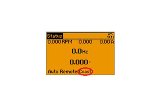
Tech support call bypass mode

This alarm appears if there is a digital input terminal programmed for the function “External Interlock” and there is not 24 Volts connected to it. A digital input terminal programmed as “External Interlock” is intended to be used as a safety terminal. When the voltage is lost or removed from the terminal, the VFD will immediately drop the output voltage to zero and the motor will coast to a stop. Follow the steps below to troubleshoot this alarm on a standalone VFD. If the following steps do not solve the problem, please call tech support for further assistance. If the drive has an integrated bypass panel, skip to the last two steps below.               

  • Locate the digital input terminal (P5-10 – P 5-15) that is programmed as “External Interlock” and program it to “No Operation”. The reset key will then clear the alarm.
  • Place a jumper wire between control card terminal 12 (24 VDC) and the digital input programmed as “External Interlock”. Press the reset key to clear the alarm.
  • If control wiring is connected to the terminal programmed as “External Interlock”, investigate why there is not 24 volts on the terminal. Look for an open in the safety circuit between the 24 volt supply and the terminal.
  • Locate the digital input terminal (P5-10 – P 5-15) that is programmed as “External Interlock” and program it to “No Operation”. The reset key will then clear the alarm.
  • Place a jumper wire between control card terminal 12 (24 VDC) and the digital input programmed as “External Interlock”. Press the reset key to clear the alarm.


Integrated bypass panel: The same procedures apply to a drive that reads “Auto Remote Coast” in the bottom line of the display. The only difference is that the digital input terminal is programmed to “Coast Inverse” rather than “External Interlock”

  • Check for continuity between terminals 5 & 6 on connector X55 of the bypass board. There must be a connection before you can reset the alarm. Either use a jumper or wire in a normally closed safety contact between the terminals.
  • Check to see if the motor overload is tripped. An alarm 60 is generated when the normally closed auxiliary contacts (95 & 96) of the overload open.

The drive requires a start command and a speed reference in order to run. If the drive has been given a start command but the motor will not run or change speed, then most likely there is an issue with the speed reference. Follow the steps below to assist you in properly configuring the speed reference to the VFD.

  • Ensure that parameter 3-15 (Reference Resource) is set to “Analog Input 53”.
  • Verify that there is voltage or current present on your input speed reference wires.
  • Set parameters 3-02 & 3-03 to the minimum and maximum desired reference.
  • Place the DIP switch behind the LCP (AI 53) in the correct position for voltage or current dependent on what type of speed reference signal you are using.
  • Connect the positive wire of your speed reference signal to terminal 53 of the control card, and the negative wire to terminal 55.
  • Use parameters 6-10, 6-11, 6-14 & 6-15 to scale your reference input to match the reference signal (parameters 6-12 & 6-13 are used for current signals).
  • View the reference % in parameter 16-50 to verify that it is changing with the signal.

Follow the steps below to determine if an alarm 14 is being triggered by the motor or cabling, or by a defective current sensor in the VFD.

  • Remove AC power from the drive and disconnect the motor.
  • Power the drive back on and reset the fault by pressing the “Reset” key.
  • Run the VFD with no motor to see if the fault appears or if the drive runs without tripping.
  • Observe the motor current in the display. It should be very close to zero with no motor connected.
  • Reconnect the motor and attempt to run the drive again.


If the drive trips on an “Alarm 14” with the motor disconnected, then the problem is inside the drive. A bad current sensor is most likely the cause of this type of fault.

If the drive runs without the motor connected, but the current shown in the display is greater than .3 amps then it has a faulty current sensor.

If the drive runs with no motor connected and the current shown in the display is less than .3 amps, reconnect the motor. Attempt to run the drive with the motor connected again. If it trips immediately on “Alarm 14”, there is likely a problem in the motor or cabling. Use a 1000 volt megger to test the motor and the motor cabling.

In the event that there is current shown in the display with no motor connected, performing a “manual initialization” of the drive might help in zeroing out the current sensors. With power off, press and hold the “Status”, “Main Menu” and “OK” keys. Power the drive back on while holding the keys for 5 seconds. The drive will power up in an alarm 80 “Drive Initialization” if you were successful. WARNING: A manual initialization will cause the drive to revert back to factory default settings wiping out all parameter changes, any fault log data and personal menu settings that have been made.

There are several things that can cause a drive to have no display when powered on. Follow the steps below in order to help solve this problem.

  • If another LCP (keypad) is available, swap them to verify that it is not the problem.
  • With AC voltage, applied, use a meter to check for DC bus voltage at the available connections. You should read a DC value that is approximately 1.35 times the incoming AC voltage. If you measure the expected DC, move on to the next step, if you don’t call Danfoss tech support.
  • Remove the control card terminal strips and see if the display appears. If it does, there is an excessive external load on the control cards’ 24 volt supply which will need to be corrected. If there is still no display, move on to the next step.
  • Depending on what size drive you are working on, there may be a small 4 amp glass fuse visible between the DC bus and the power card. If you find that this fuse is blown, the switch mode power supply located on the power card is defective and will need replacement. If the fuse is located and tests good, move on to the last step.
  • Replace the control card with another one and see if the drive powers up and the display is visible. Any control card from the same series drive will work for this test, so if there is another drive available you can try the CC from that drive.


Current limit warnings appear when the drive reaches the current limit set in parameter 4-18. The value of parameter 4-18 is set as a percentage of entered motor nameplate current (P 1-24). Sometimes current limit warnings occur due to application issues, and other times due to incorrect parameter settings.

There are several things that can cause this warning to appear, review the information below

  • Check parameter 4-18 to see if it adjusted to the correct setting, the default is 110%.
  • Check to ensure that the correct motor data has been entered in parameters 1-20 thru 1-25.
  • Check that the “Ramp Up” and “Ramp Down” times are not excessively short. Parameters 3-41 & 3-42 are used to adjust these settings. Attempt to increase the ramp times to see if the problem goes away.
  • Set parameter 1-03 to the value “Variable Torque” and see if the problem disappears.
  • Check the application for problems such as bad bearings, load binding or excessive mechanical load.

When a powercard is replaced, some initial programming must be done before the drive can be used. The spare part programming instructions are below.

Purpose

Instructions to enter typecode data into parameter 14-23 after a new power card has been installed in the drive.

General

Install the replacement power card  in accordance with the procedure in the unit service manual. Be sure  to comply with proper ESD  procedures when  handling the power card.

Once  the new  power card  is installed, it is necessary to reconfigure the drive  by entering the 39 unit typecode which  is printed on the drive  label.  The 39 units  are divided into 19 index  groups (see Table  1).

Here  is a sample typecode configuration for a 132 kW, 380-500 volts,  FC-202 with options. FC-202N132T4E21H2XGCXXXSXXXXAXBKCXXXXDX

NOTE: Changing out the power card causes the drive to lose all programming. If possible, upload parameter settings to the LCP prior to replacing the card.  If not, reprogramming the unit after power card installation is necessary.

Procedure

1.  Install the new power card.  See the Service Manual for the unit for instructions.

2.  Record the typecode of the unit being serviced (Fig. 1). The typecode (t/c) is listed on the label of the unit (see Fig. 2).

3. Apply power to the unit.

4.  Upon power-up completion, Alarm 250 New Sparepart will appear on the unit display. To clear this alarm, the typecode information must be entered in parameter 14-23, Typecode Setting.

5. To access parameter 14-23, Typecode Setting, press the main menu key on the unit control panel.

6.  Use the arrow and OK keys to scroll to parameter group 14 and parameter 23.

7. Parameter 14-23 is an array parameter (see Fig 3). Scroll through the submenu to match the 39 characters in the typecode in the 19 index groups. Press the OK key to enter the value.

8. At index number 20, enter Save to EEPROM and press the OK key. (The display returns to No Function at the completion of writing the EEPROM data.)

9. Alarm 250 New Spare part on the unit display will change to Alarm 251 New Type Code. To reset alarm 251, remove power to the unit, then reapply power. Press the RESET key to clear the alarm.

NOTE: It is recommended that the motor leads be disconnected and the unit operated to check functionality prior to running the motor.

Contact Danfoss technical support in the event that an alarm 38 appears. This problem occurs when there is a communication error between the control card and the power card.

9. The VFD will trip and an “Alarm 29” is displayed when the measured temperature of the inverters heat sink exceeds the upper limit. This can be caused by a number of things. Use the information below to assist you in identifying the problem.

The first step is determining if the fan is running or not. The cooling fans on a Danfoss VFD run for about 5 seconds after it is powered on by the mains. Remove AC power from the drive and wait until the display goes dark. Power the drive back on while observing the fan. If it runs momentarily, then it’s not likely to be the problem. Review the information below for other things that may be causing the over temperature. If the fan did not run   momentarily when the drive was powered on skip to the next paragraph. On the FC series drives, parameter 14-52 can also be used to turn the fans on                            

  • Gain access to the back of the drive and inspect the heat sink. If material is built up and obstructing airflow across the fins, it will need to be cleaned.
  • Verify that there is adequate room above and below the drive for proper cooling.
  • Verify that the ambient temperature of the area where the drive is installed is within the limits (113 degrees F).
  • Read the heat sink temperature of the drive by viewing parameter 16-34. The the trip point occurs at 95 degrees C.

If the fan did not run for approximately five seconds after power up, either the fan or the fan power supply is defective. In drives 150 HP and below, a simple test can be done to determine where the problem lies. Set a multimeter to the DC volts position and apply it to the connector that the fan plugs in to. While observing the meter, power on the drive and look for voltage. If no voltage appears when the drive is powered on, the fan power supply is defective. If voltage is present, but the fan does not turn the fan is the suspect problem.


10. The VFD trips on alarm 4 when there is excessive AC ripple on the DC bus. Refer to the procedures below to determine if the problem exists in the drive or with the input mains voltage powering the drive.                            

The VFD can be run at about 50 percent of its current rating before it will trip on an alarm 4. The tests performed when troubleshooting the drive must be done while the VFD is under load. Cycle power to the drive and press the “Reset” key to clear the alarm. Press the “Hand On” key to start the drive locally. Slowly increase the speed by using the up and down arrows on the keypad. Continue to increase the speed until the drive trips on alarm 4, and note what speed the trip occurred at. You will need to reset the alarm and run the drive again, but this time bring the speed to a point slightly lower than where it tripped last time.

  • Using a volt meter, measure the voltage between all three input phases to verify that they are all within 3% of one another. If the imbalance is greater than 3%, it could be the cause of the alarm 4. If they are balanced, move on to the next step.
  • Using a clamp on ammeter, measure the current in each of the three input phases and note which phase is imbalanced.
  • Remove the mains power from the input of the VFD. Swap the input phase that had the low current reading with one of the other two. Power the drive back on and run it at the speed that it will reach without tripping. Measure the input current again with the clamp on ammeter. If the low phase followed the wire that you swapped, then the problem is most likely associated with the input power to the VFD. If the low phase remained in the same position after the swap, the VFD has a fault rectifier section and you will need to call Danfoss tech support for further assistance.