The secret behind Danfoss adaptive defrost

Tuesday, May 5, 2020

Before digging into the secret of Danfoss adaptive defrost, let’s first take a look at the most common methods of defrosting refrigerated display cases, and why they’re necessary.

Why is defrost necessary?

Ice can form in refrigerated display cases due to several factors such as humidity, evaporator surface temperature, and even air flow. If display cases aren’t regularly defrosted, ice can build on the evaporator and air flow will be restricted or stop altogether—resulting in reduced and inefficient cooling.

Poor airflow will result in high display case temperatures, generating high temperature alarms. High air temperatures over long periods will harm food quality and can often lead to food loss.

But while defrosting is necessary for safe and efficient operations, there’s a balance that needs to be struck.

Infrequent or short defrost cycles can also cause ice to build on the evaporator—risking a premature service call. Whereas too many defrost cycles performed for too long can have a negative impact on food quality. This can also create excess energy consumption.

Why is adaptive defrost so smart?

Because humidity, ambient temperature, and air flow can vary significantly—due to overfilling or cold room doors left open—even an optimum defrost schedule can’t fully account for the wide-ranging operating conditions.

That’s why an adaptive defrost control algorithm is needed to ensure the right number of defrost cycles are carried out based on real-time conditions.

Typical methods of defrosting (state-of-the-art)

Danfoss AK-CC evaporator controllers feature a flexible defrost control function that allows users to set up a variety of defrost methods, along with a range of defrost start and stop methods.

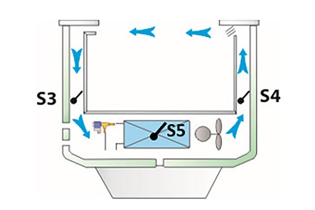
Danfoss AK-CC controller temperature sensors and their placements:

S3 air on evaporator—return air sensor

S4 air off evaporator—discharge air sensor

S5 defrost stop—defrost termination sensor

Air/off cycle defrost

The best way to melt ice depends on cabinet design and temperature level. In medium temperature (5 °C) applications, ice can be melted by pausing refrigeration, allowing the fans to just circulate air.

Electrical or hot gas defrost

In low temperature applications where the temperature target is around -18 °C, ice can only be melted using a heat source—typically an electrical heater mounted close to the evaporator fins or hot gas circulated inside the evaporator tube.

defrost methods

Defrost interval timer

The simplest defrost start method uses a defrost interval timer, which is reset after each defrost cycle.

It also makes sense to use an interval timer as a back-up for other defrost start methods. For example, if a digital input from an external device is used to start a defrost cycle twice a day and the signal is interrupted, then setting the defrost interval timer to perform an emergency defrost 16 hours after the last cycle can help protect the system.

Defrost schedule

This is the most common defrost start method and can be initiated either from the front end using bus communication or the built-in defrost schedule. By using a schedule, defrosts can be performed outside peak hours or when a store is closed.

Maximum thermostat runtime

A less common defrost start method, maximum thermostat runtime uses accumulated refrigeration time between defrosts.

Manual or external defrost start

Defrost cycles can also be initiated using a digital input, an app, or the defrost start/stop button on setting displays.

All defrost start methods can be used in parallel.

Time

After selecting a defrost method, it’s important to select an appropriate defrost stop or termination method.

When using air circulation in medium temperature cabinets, it can be enough to just circulate the air at a set time. But electrical or hot gas defrost cycles need more sophisticated stop methods to avoid overheating the cabinet when the ice has melted.

S5 defrost sensor or S4 discharge temperature sensor

Often, a defrost stop or termination sensor is placed on the evaporator where ice is typically formed. By monitoring the temperature signal during defrost, the cycle can be stopped when the sensor reaches a set temperature.

Danfoss AK-CC controllers have a maximum defrost time setting that’s also used as a safety function in combination with other defrost stop methods.

Manual defrost stop

Defrost cycles can also be stopped manually via the front end, an app, or the defrost start/stop button on setting displays.

Too frequent or extensive defrost cycles can have a negative impact on food quality and system efficiency—risking unsafe food temperatures and unforeseen temperature alarms. In addition, a system will use more energy to reach its target temperature after a defrost cycle.

Using adaptive defrost mode, combined with an S5 temperature sensor, can help optimize defrost cycles.

The Danfoss adaptive defrost algorithm detects the amount of ice build-up and can be set up to either cancel a scheduled defrost, or only perform a defrost if evaporator air flow is interrupted by frost or ice.

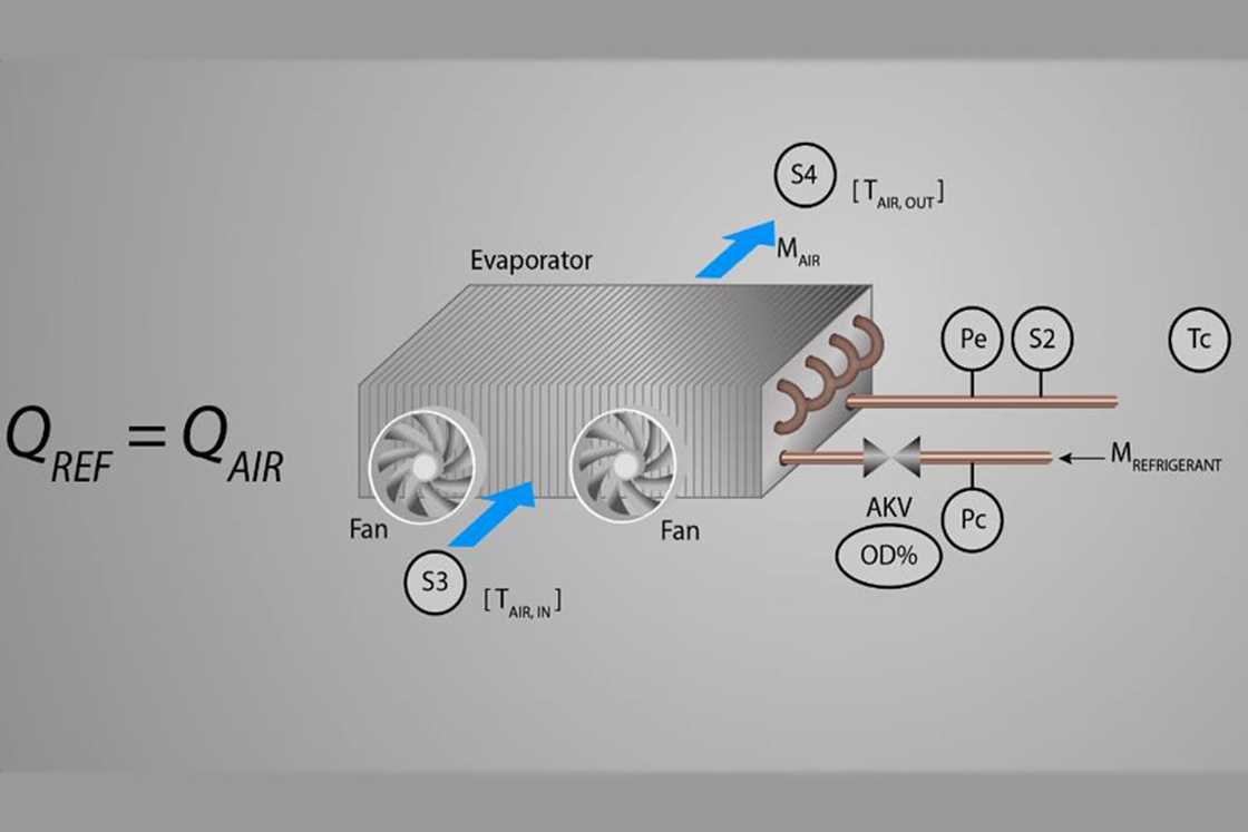
The concept compares energy uptake on the refrigerant flow side with energy emissions on the air flow side. For example, when the evaporator is clear of ice, an energy balance is assumed. Whereas an imbalance can be identified when ice builds on the evaporator surface—resulting in restricted airflow.

The energy flow calculation and comparison between refrigerant and airflow depends on a variety of existing sensor signals and controller data:

  • Refrigerant side—Tc condensing temperature from the pack controller distributed via the front end. Pe Evaporator pressure, S2 coil out temperature, and OD% opening degree of the electronic expansion valve.
  • Air flow side—S3 air on evaporator (return air), and S4 air off evaporator (discharge air).

Monitoring

Monitoring can be set up in parallel with other defrost methods to generate an alarm in case of restricted air flow or evaporator icing. A flash gas alarm can also be activated to indicate refrigerant flow issues.

Adaptive skip day

Adaptive skip day enables the controller to cancel and skip defrosts that are scheduled in the daytime, leaving defrosts to continue overnight uninterrupted.

Only defrosts that are configured using the schedule in the front end or configured via the internal defrost schedule in the controller can be skipped.

Adaptive skip day and night

In an adaptive skip day and night configuration, the controller can skip scheduled defrost cycles 24 hours a day.

But for safety reasons, only a maximum of three consecutive defrosts can be skipped—with the fourth being performed regardless of the amount of ice present.

Full Adaptive

Full Adaptive mode is the optimum choice for applications where a defrost isn’t requested  at a certain time, but can be performed when ice interrupts the airflow. It’s recommended that this mode is combined with a defrost interval timer or scheduled defrost as a safety precaution.

Manual defrost can always be performed independently to your selected defrost method.

Adaptive refrost
  • Always use the defrost interval timer in combination with other defrost start methods to help ensure safe operation.
  • When terminating a defrost cycle based on an S5 or S4 temperature, it’s important to ensure the maximum defrost timer is set for longer than you anticipate the ice to melt and reach the defrost stop temperature. If the maximum defrost time is too short, each defrost will trigger an alarm.
  • If ice formation varies from case section to case section, adaptive defrost with defrost coordination isn’t recommended.
  • When selecting defrost skip, it’s recommended to set your defrost schedule for peak demand. For example, the number of defrosts that are needed for the highest humidity levels—enabling the controller to automatically skip additional defrost cycles when possible.
  • Full adaptive defrost can be used in combination with other defrost start methods and will only add a defrost cycle as it’s needed.
  • Adaptive defrost doesn’t impact or use defrost stop.
  • The stop method and related timers still need to be optimized for different applications.
  • Appropriate defrosting periods need to be set based on individual conditions and the application.

Background

To understand the underlying logic of adaptive defrost it’s important to first understand the concept of energy balance. Energy balance is about bookkeeping energy and it follows the first law of thermodynamics—energy cannot be created or destroyed, but it can be changed.

Applying this law to an evaporator in a supermarket means that when heat that’s flowing across the evaporator/heat exchanger is removed, it needs to be added to the refrigerant flow. When air flows across the evaporator, the temperature or “energy content” of the air is reduced.

According to the first law of thermodynamics, this reduction ΔQair must correspond to the energy increase experienced by the refrigerant ΔQref. Put in mathematical form, this means that:

Equation 1: ΔQair = ΔQref => mairΔhair = mrefΔhref

Where m denotes the mass flow rate and the subscript denotes the medium (air or refrigerant), the change of enthalpy across the heat exchanger on the air and the refrigerant side respectively is denoted by Δh.

Frost detection principle

When frost forms on a heat exchanger, the air flow across the heat exchanger is reduced—this includes a reduction in mass air flow. But airflow isn’t measured, meaning it can’t be used for frost detection.

The mass flow rate of the refrigerant—and the enthalpy difference across the evaporator on the air and refrigerant side—can all be calculated using information and sensor data available in the case controller. This means that an estimation of the frost-free mass flow of air can be achieved using the energy balance equation:

Equation 2: mair.icefree = mref.icefreeΔhref.icefree / Δhair.icefree

In practice, this estimated ice-free mass flow can be achieved just after a defrost cycle and is used as a baseline for the expected mass flow across the heat exchanger. This means that the frost detection checks whether the mass flow has dropped compared to the baseline.

Mathematically this is done by checking the energy balance—assuming ice-free conditions—as follows:

Equation 3: mair.icefreeΔhair = mrefΔhref

Note: The equality sign in equation 3 is true when the evaporator coil is frost-free. As soon as ice starts to form on the coil, the mass flow of air reduces and the left side of the equation becomes larger than the right.

This imbalance is what the adaptive defrost algorithm uses as an indicator for frost build-up.

The principle of frost detection using the energy balance can be compared to a scale:

Step 1: The scale is adjusted to balance when the coil is frost-free just after a defrost.

Step 2: As more ice builds on the evaporator coil surface, the measured heat uptake on the refrigerant side decreases compared to what’s expected from an ice-free evaporator coil. Eventually the scale tips over and a frost detection is signaled.

To illustrate how the adaptive defrost algorithm functions, we passed data from a laboratory experiment through the algorithm.

The purpose of the experiment was to generate data from an evaporator while ice was built up from the ice-free evaporator until the airflow through the evaporator was blocked.

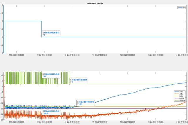
Fig. 1 shows the data from the experiment and the output from the adaptive defrost algorithm. The blue and red curves on bottom show the air temperature entering and exiting the evaporator.

The cut-in and cut-out temperature limits for the thermostat are also shown in the plot in yellow and purple. In addition, a state variable of the controller is plotted to indicate whether the evaporator is cooling or warming up.

The top plot shows the output from the adaptive defrost algorithm—where “1” is a defrost request. Ice could be detected at least 24 hours before the temperature crosses the upper limit of the thermostat band.

At the detection time, it’s hard to see by looking at the temperatures that a defrost is required. But by looking at the control state variable, it shows that the thermostat duty cycle increases significantly after the point where the adaptive defrost would have requested a defrost—meaning that evaporator performance has decreased.

The adaptive defrost algorithm ensures that a defrost will be executed as soon as evaporator performance starts to degrade.

Adaptive refrost algorithm

For a refrigeration system to deliver consistently high performance, continuous adaptation to changing operating conditions is critical, to help eliminate evaporator coil frost formation and ensure good overall system performance.

A high performing, frost-free evaporator coil—combined with an optimal injection control such as the MSS or ALC—helps to ensure that evaporation temperature is maximized for optimal heat exchange between the coil and passing air, and ensures that accuracy is maintained.

For a system to operate effectively at a high evaporation temperature, the adaptive Po-optimization must be applied to help the system operate with the highest attainable suction pressure, thereby minimizing the power consumption of the compressors.

Several adaptive layers of intelligent controls help to secure consistently high system efficiency. Every layer operates independently and continuously adapts to conditions by achieving maximum performance from even a low-performing evaporator coil.

Adaptive defrost—in combination with defrost stop on temperature—helps to guarantee the optimum number of defrost cycles to keep the evaporator free of ice.

Simply, adaptive defrost can help you strike the perfect balance between maintaining optimum food quality and energy efficiency.

Download PDF

Find more information about our solutions

  • if (isSmallPicture) { The same image used in "supermarket solutions" but cropped slightly differently; } else if (isBigColumns) { The same image used in "supermarket solutions" but cropped slightly differently } else { The same image used in "supermarket solutions" but cropped slightly differently }
    Case controls

    Your refrigeration system is the natural place to look for energy efficiency gains. To unlock that potential, you need a controller, expansion valve, and high accuracy sensors that are smart enough to make the technology work together—and a system manager that can help you see and control the bigger picture.

  • if (isSmallPicture) { An animated image of the utopian smart store full of connected solutions within your neighborhood grocery store; } else if (isBigColumns) { An animated image of the utopian smart store full of connected solutions within your neighborhood grocery store } else { An animated image of the utopian smart store full of connected solutions within your neighborhood grocery store }
    Smart store

    The Smart Store solution enhances food safety and brings down the energy bill by integrated and smart control of refrigeration, HVAC, lighting and other applications.