Manufacturers and owners of heat pumps are always concerned both to maintain an optimum evaporator charge, even at highly fluctuating ambient temperatures, and to increase energy efficiency by keeping evaporation temperatures as high as possible, but with the usual thermostatic expansion valves it is often not possible to give these requirements the attention they deserve. Electronic expansion valves, however, are ideal for this purpose.
Low super-heat – Higher evaporation pressures – Increased COP
The advantages of electronic super-heating control are obvious. The evaporator is always optimally filled with refrigerant. The amount of refrigerant to be injected can be dosed precisely even under conditions of extreme temperature fluctuation (i.e. for a wide range of ambient temperatures). This is achieved by continually passing the current value of the super-heat in the evaporator via a pressure transducer (marked "P" in the diagram) and a sensitive temperature sensor ("S2") to the "EKD 316" control unit for heat pump manufacturers, thus enabling it to take appropriate measures to achieve optimally low super-heating. This adaptive control of the refrigerant injection ensures optimum use of the evaporator and hence the highest evaporation pressures that can be realized in the particular system, thus improving the COP and using energy more efficiently.
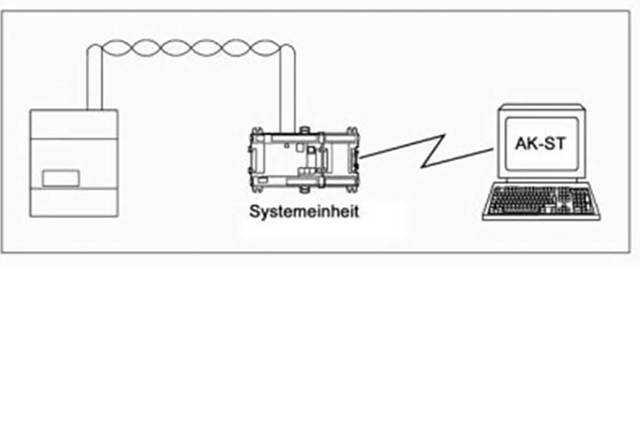
The control unit is operated by means of two pushbuttons on an optional display. This enables the heat pump manufacturer to decide whether to simplify service technicians’ access to the control unit (with an external operators’ display integrated into the heat pump) or – to prevent unauthorized tampering and unwanted program modifications – to simply present the control unit as a black box. The two buttons, coupled with a three-character display, are entirely sufficient for programming the control unit and displaying all the important data. Using the operators’ display unit, the service technician can intervene in the control cycle or have relevant information displayed. The unit’s menu not only shows the basic configurable parameters, such as the type of refrigerant, it is also possible to adjust the stability and amplification factors so as to precisely influence certain processes. This applies, for example, to the superheating control, making it possible to prevent the superheat value from oscillating. It is also possible to choose between adaptive and load-dependent superheating regulation. Adaptive superheating regulation has already been described here in some detail. Load-dependent superheating regulation deliberately operates with higher superheating values for certain partial load situations, for example to ensure longer minimum running times for the compressor, or to reduce frost build-up on the evaporator in air to air or air to water heat pumps, thereby possibly reducing the necessity for defrosting. For the initial production-line programming of the control unit we recommend the software service tool (AK‑ST500). This program accesses the control unit via an optional system unit and makes the initial programming a matter of moments. The same software package can also be used for other servicing activities.
Service technicians will find the service menu of the electronic superheating control unit particularly useful, both for commissioning the system and for subsequent servicing. Those parameter values that begin with “u” show the system’s current values, which are vital for diagnosing all kinds of faults and for assessing the state of the system. Particular attention should be given to the values of the three displayed parameters “superheat”, “temperature at S2 sensor” (that is at the evaporator outlet) and “evaporation temperature”, which together indicate the current system state. For one thing, they are easy to read out and do not need to be laboriously determined with a service manometer and technician’s temperature measuring device, and it is also possible to immediately see what values the controller is using. When working with electronic systems, in order to avoid having to laboriously track down faults caused by sensors misreading the actual values, the standard procedure for an experienced installation technician is to check all the sensors before commencing to take the system into operation (for ordinary resistance sensors this is quite easily done with a simple ohmmeter: a PT1000 sensor at 0°C has a resistance of 1000 Ω). A glance at the service menu makes it possible to dispense with this, because you can immediately see whether a value is realistic or not (and, if you are unsure, can check the reading yourself with a thermometer or manometer).
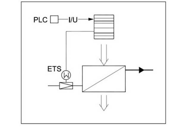
Naturally, the outputs from the control unit are just as important as its inputs. In order to simplify this particular point when commissioning the system, the control unit menu makes provision for a manual override on the outputs from the “ETS” valve and the alarm output. One typical problem with control equipment is determining whether an output is not being switched because for some reason the control unit considers this to be unnecessary, or whether it cannot be switched, e.g. because it is defective. Even experienced service technicians have spent many hours wrestling with this problem. For this reason we recommend that when commissioning a system you always check each of the relevant outputs individually, one at a time. This will enable you to rapidly eliminate wiring and correspondence faults.
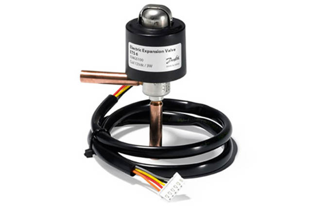
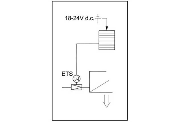
The “ETS” unit is an analogue valve that is preferred in situations where every degree of super-heat counts and even the smallest deviation in the evaporation pressure is to be avoided. The unit can be used as a P, PI or PID controller. P regulation is a standard regulation that depends on the deviation (for example, if the super-heating gets too high, the valve opening is always increased at the same rate). For PI regulation it is possible to separately modify the integral action time (that’s the “I contribution”). This means that we can change the speed at which the regulator reacts, making it more sensitive or more sluggish. Either may be necessary. For a PID regulator, the “D contribution” also optimizes the control characteristics in the event of sudden changes in a set-point. Where an “ETS” valve is used there should also be provision for a UPS (uninterruptible power supply). This is absolutely vital, because in the event of a sudden voltage drop the “ETS” opening will stay at its current position and refrigerant will continue to be injected into the evaporator, possibly causing considerable damage or even complete failure of the compressor unit. If there is a UPS, then even in this situation it will always be possible for the valve to be closed.