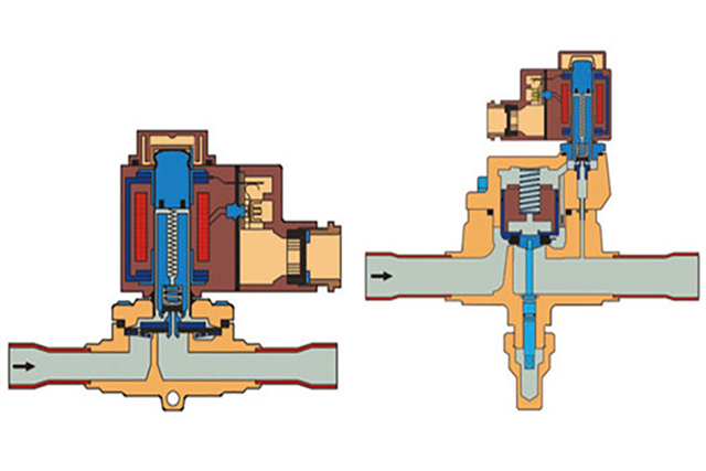
Dimensioning of refrigeration components - part 1: solenoid valves

Monday, 21 November, 2011

In the modern world of refrigeration systems, increasingly greater emphasis is placed on energy efficiency and sustainability. Electronic control systems are often the center of focus here, but it should not be forgotten that the dimensioning of refrigeration components can also make an important contribution to reducing operating costs in refrigeration systems. This is based equally on reducing pressure drops and preventing system malfunctions. The subject of this edition is the correct dimensioning of solenoid valves for refrigerant as the medium.

Function

To be able to dimension a solenoid valve correctly and to know what to keep an eye on as you do so, we will now first of all take a look at the set-up of these refrigeration components. Generally speaking a solenoid valve consists of a coil and a valve housing. The coil is mounted on an armature tube. With smaller, directly-controlled valves, the movable armature opens and closes the valve by directly releasing or closing the valve seat. To achieve a better internal seal, that part of the armature that contacts with the valve seat must be given a Teflon seal disk. With servo-controlled solenoid valves the armature movement happens the same way, but in this case a servo bore hole is opened or closed, instead of the entire valve seat. In the case of servo valves with a diaphragm, this results in a movement of the diaphragm over the differential pressures on the valve, which then corresponds with the valve's opening and closing process. The principle is the same with servo solenoid valves with pistons and without a diaphragm. The valve is also opened and closed via the servo bore hole here - but using the piston mechanism, and not with a diaphragm. A rough classification according to capacity values is easily possible. The solenoid valves with the smallest capacity values are therefore mostly directly controlled. With bigger systems, there are also valves that are all fitted with diaphragms and servo-controlled. Ultimately with high capacities you will find servo-controlled piston valves. If these values are no also longer sufficient, then main valves can easily be turned into solenoid valves by means of a solenoid valve attachment. These combinations then leave practically no requirements unfulfilled with regard to the size of the system. If you open a solenoid valve and find neither a diaphragm nor a piston in it, then it will generally be a directly controlled valve. This will then have smaller connections, such as 6, 8 or 10 mm.

Why is it important at all to know if you are dealing with a directly-controlled or a servo-controlled solenoid valve? This point is actually critically important for dimensioning valves. Directly-controlled solenoid valves do not require any minimum pressure drop for operation. These valves therefore have an extremely good partial load capacity, which allows a moderate pressure drop to be configured. The same dimensioning criteria as with directly-controlled valves also apply to assisted servo-controlled valves. There is no minimum pressure drop that has to be taken into account here either. With servo-controlled valves on the other hand, in addition to the maximum pressure drop, the minimum partial load case must also be considered. With a minimal partial load, the pressure difference must not be allowed to fall below the minimum value that the valve requires in order to be able to work reliably. 

This minimum pressure difference of the valve is shown in the relevant technical datasheets. Example: The "EVR 10" has a required minimum pressure drop of 0.05 bar. With 20 kW cooling capacity, R134a and 10°C evaporation, i.e. normal cooling, and an installation in the liquid line, the "EVR 10" would be not be a bad first choice, because 0.06 bar pressure drop in full load is above 0.05 bar, and therefore fine. If now, however, two same size 10 kW compressors are activated in the system on this cooling circuit, only one compressor then falls below the minimum pressure drop when in operation. Mathematically there would then be a pressure drop of only 0.02 bar. The smaller valve should therefore be preferred in this case. 

With "EVR 6" the valve's minimum pressure drop is also 0.05 bar, the full load pressure drop is 0.36 bar, and the partial load pressure drop is 0.09 bar. Both values are greater than 0.05 bar. The valve therefore works in every likely operating state. The valve capacity value is therefore determined. A solenoid valve value generally offers the option of selecting different pipe connection widths to minimize the use of reducing sleeves. The sample valve is therefore available with connections for 3/8” or 10 mm and 1/2” 12 mm copper pipe. 

If, despite intensive efforts for full load cooling capacities, with which servo solenoid valves would usually be used, no suitable valves could be found because the partial load is too low, technically a switch can be made to a corresponding main valve or motor valve. Small main valves (e.g. ICS type with pilot solenoid valve) and motor valves (ICM) are very good partial load options, and can often also still be used if the corresponding partial loads can no longer be run with the standard solenoid valves. The disadvantage of these alternatives is the higher price compared with the standard solenoid valve. Another solution for such partial load instances can be provided by assisted servo-controlled valves (minimum pressure drop 0 bar). These valves, such as "EVRAT" and "EVRST" were originally designed for ammonia, but they can also be used for "copper refrigeration".The ideal dimensioning of a solenoid valve for the minimum required pressure drop with the minimum possible partial load of the system and with full load is therefore still a moderate pressure drop. The section of the dry expansion refrigeration system that the solenoid valve is installed in is crucial for the dimensioning. This is the liquid line in most cases. In addition to this, however, there are also the suction line, the hot gas line and the hot gas bypass line.

The size of the required solenoid valve also varies with different system subcooling values. So with otherwise identical system data, you need a bigger valve with smaller subcooling (e.g. 3K) than at 30K, for example. The is due to the information that is usually available for the dimensioning. The pressure drop of a valve mainly depends on the volume flow. This specification is, however, (at least in commercial refrigeration) unusual. In fact, only the cooling capacity, refrigerant and evaporation temperature are available for the dimensioning. The subcooling and condensing temperature are often already the first two estimated values. In practice it is not relevant whether the subcooling is 3 or 4K, but it is with 4 or 30K. The degree to which an solenoid valve can be smaller when the refrigerant is additionally sub-cooled by 35K can be seen from the correction factors when dimensioning using datasheets. In cases such as this the required size of the solenoid valve can be reduced by a third (correction factor - 0.65). This can be attributed to the correlation of the cooling capacity with the enthalpy difference and the mass flow, which in turn is composed of the volume flow and density. The mass flow multiplied by the enthalpy difference is the cooling capacity. If the enthalpy difference now increases because of subcooling, the mass flow becomes smaller with the same cooling capacity. As the density remains the same, the volume flow is reduced. This results in a lower pressure drop. If this is ignored, the dimensioned servo valve could produce a full load pressure drop below the required minimum. The valve would therefore constantly open and close and a device failure would be inevitable. The flow rate through the valve would also be insufficient.

Correction factors based on liquid temperature t1 

t1◦C -10 0 10 15 20
R134a 0.73 0.79 0.86 0.90 0.95
R404A/R507 0.65 0.72 0.81 0.86 0.93

When dimensioning solenoid valves, you should always check the maximum permissible working pressure. This is especially important with refrigerants with higher pressures, such as R410A or R744 (CO2). As an educated guess, the maximum permissible working pressure with R410A should be at least 40 bar. With the standard refrigerants, R404A, R507, R407C and R134a, 32 bar is absolutely sufficient for use in the liquid line or hot gas line. Theoretically, this value need only correspond with the dimensioning pressure of the system (or system section). 

One point that is easily overlooked when selecting solenoid valves is the "MOPD". "MOPD" is the "maximum operating pressure differential" that can be produced with the valve-coil combination in question. This "MOPD" essentially depends on both the solenoid valve type and the coil used. For example, an "EVR 3" with a 10W AC coil with maximum 21 bar differential pressure can work with a 12W AC coil right up to 25 bar. This point is not a problem with use in the liquid line and in normal cooling operation. But, for example, if closing the solenoid valve then causes suction and the system shuts down via the low pressure switch, the full differential pressure between the high and low pressure side will be exerted on the solenoid valve. The "MOPD" must be big enough to be able to open again against this pressure difference. 

Minimum needed pressure drops and MOPD

     Opening differential pressure with standard coil Δp bar          
               
Type   Max.(=MOPD)liquid2)     Temperature of medium Max.working pressure PB kr value1)
  Min. 10 W a.c. 12 W a.c. 20 W d.c. °C bar m3/h
EVR 2  0.0  25    18  -40-> 105  45.2  0.16
EVR 3 0.0  21   25 18    -40-> 105 45.2  0.27 
EVR 6 0.05  21  25  18    -40-> 105 45.2  0.8 
EVR 6 NO 0.05  21  21  21    -40-> 105 35   0.8
EVR 10  0.05 21  25  18    -40-> 105 35   1.9
EVR 10 NO 0.05  21  21  21    -40-> 105 32   1.9
EVR 15 0.05  21  25  18    -40-> 105 32   2.6
EVR 15 NO 0.05  21  21  13    -40-> 105 32   2.6

EVR 20 (a.c)

0.05  21  25  16   -40-> 105  32   5.0

EVR 20(d.c.)

0.05     16 -40->105 32 5.0
EVR 20 NO 0.05   19 19  19   -40-> 105   32  5.0
EVR 22 0.05  21  25  13   -40-> 105  32   6.0
EVR 22 NO 0.05  19   19 19   -40-> 105  32   6.0
EVR 25  0.20 21  25  18   -40-> 105  32   10.0
EVR 32 0.20  21  25  18   -40-> 105  32   16.0
EVR 40 0.20  21  25  18   -40-> 105   32  25.0

To correctly dimension a solenoid valve for a refrigeration system, with servo valves the actual pressure must always be higher than the minimum pressure drop. This applies to all partial load states. The pipe connection size can only be selected when this is ensured. If, in addition to this, the fitter also consider a sufficiently high "MOPD" and maximum working pressure, he or she will be rewarded with a reliably working solenoid valve with maximum service life.