Remote control units

  • Overview
  • Tools and apps
  • FAQ
  • Case studies

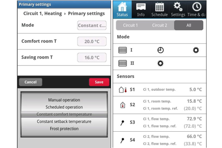
In case of limited access to the basement or heating system, the electronic controller (ELC) can be supplemented with a remote control unit, ECA 30/31, which can be placed at any desired location in the building.

This enables room temperature monitoring and control, easy interfacing, and remote access for overriding all the functions of the ECL Comfort controller.

The remote control units ECA 30 and 31 are used for room temperature control and override of the ECL Comfort 210 and 310 controllers.

The remote control units are connected to the ECL Comfort controllers by means of x2 twisted pair cables for communication and power supply (ECL 485 communication bus).

The remote control unit ECA 61 is used for room temperature control and override of the ECL Comfort 110 controller. The DLG is a gateway used for linking ECL Comfort 110 with Danfoss Living™ radiator thermostats.

Features and benefits

Can be placed at any desired location in the building

Enables monitoring, control and easy interfacing of the ECL Comfort controller

11 - 15%, or more, savings on your energy consumption in the building, as well as reduced CO2 emissions.

Tools and apps

Software tools

FAQ

The ECA 32 is placed in the base part of the ECL 310. Communication with the ECL 310: A 2 x 5 male-pin arrangement on the back of the ECL 310 controller connects to the related 2 x 5 female-pin arrangement on the ECA 32, when the ECL 310 is placed in its base part.

Temperature sensors, pulse inputs and analog outputs are connected via the terminals 49 - 62. 4 x relay outputs are via the terminals 39 - 46.

ECA 32 is used only together with ECL 310 and applications having ECA 32 related functions.

Besides, ECA 32 can be used as a monitoring module:
6 x temperature sensor inputs (Pt 1000) ECL 310. In the ECA favorite display the ECA 31 will show the relative humidity.

Max. 2. This limitation is because of the power demand from each ECA 30.

In the heating circuit control in the ECL 210 / 310, the parameters 1x182 and 1x183 are set to 0.0.
T. room is still displayed.

A listener is a slave controller with address 0 in a master - slave system. A listener receives T. out, time and date from the master. A listener cannot be used with an ECA 30/31.

ECA 30/31 cannot communicate with with address 0!

When uploading an application in the ECL 210 / 310 controller, the communication between ECA 30 and the ECL is slow.
When the application has been uploaded in the ECL controller, the ECA 30 will be updated and have a much quicker reaction.

No!
The ECA 30 / 31 is developed for being used with the ECL 210 / 310 series.

Procedure for setting up ECL Comfort controllers (B - types) with one ECA 30.

Example:
3 controllers, ECL 210 B (without display and dial)
One master: Application A266
Two slaves: Application A260, addresses numbers 1 and 2.
One ECA 30.

Demands:
- The master must send T.out to slaves
- ECA 30 must be used for setting all 3 x ECL 210 B controllers
- ECA 30 must be used for monitoring

It is assumed that all connections for sensors, ECL 485 bus, actuators and pumps are done.
The outdoor temperature sensor must be connected to the base part of the master controller.

Procedure:
1. Don't place any ECL controllers in any base part.
2. Connect the ECA 30 to the ECL485 bus (cable type: 2 x twisted pair)

Be sure that the ECL485 bus connections share the common terminal (30) and +12 V (31) for all the base parts with the ECL485's A and B connections.

3. Insert in its base part the ECL controller which must be addressed with the lowest slave number, for example "1".

4. Power up the units. The ECL and ECA 30 are assumed to be new from factory.

4.a. If the controller is not new from factory, do following:
In ECA 30:
> ECA MENU, > ECA factory > Reset ECL addr. > Reset ECL addr. > "Yes".
After 10 sec the ECA returns to "ECA factory" menu. The ECL address has now been set to 15. (See extra info "Reset ECL address" at the end of this document).

4.b.If the ECA 30 is not new from factory, do following:
> ECA MENU, > ECA factory > ECA default, > Restore factory, > (Choose factory), > "Yes".
This will ensure that the ECA has address A and it is connected to address 15 which is required in order to install an application in the ECL controller.

5. Insert the appl.-KEY A260 in the ECL controller (the slave)

6. Choose language

(the reaction time during steps 5 - 11 seems slow. This is because the ECL controller and the ECA 30 are not fully synchronised)

7. Choose application (not possible for A260 because only one subtype exists).

8. Set time and date

9. Choose "Next"

10. Display shows shortly "Application A260.1 installed"
- the application is uploaded.
- the display in the ECA 30 is not illuminated for 10 sec.

11. The display shows an application related menu.

12. After 10 - 30 seconds a menu "Copy application" appears (the ECA 30 must know the ECL application)

- Choose "Yes"
(the "Copy" procedure takes some minutes)

13. (Giving the slave an address number)
a. Select an ECL menu
b. Choose MENU
c. Choose "Common controller settings"
d. Choose "System"
e. Choose "Communication"
f. Choose "ECL 485 addr."
g. Select "ECL 485 addr."
- ID = 2048, factory set value is "15"
h. Change the address to the planned address number for this slave
i. After 5 sec, the chosen address number changes to a "0"
j. After further 5 sec, the display returns to "ECA MENU"
- in addition, a controller icon with a cross is present.
This means that there is no communication between the ECL controller and the ECA 30. A master is not present on the ECL 485 bus.

14. (Next ECL set-up)
Insert in its base part the ECL controller which must be addressed with the next slave number, Ex. "2"

15. (Setting the ECA to communicate on address 15)
a. Choose the ECA MENU
b. Choose "ECA system"
c. Choose "ECA communication"
d. Choose "Connection addr."
e. Change to "15"
The "key insertion animation" from the ECL controller will now be shown on the ECA 30.

16. (application upload)
Follow points 6 – 13
If slave 1 and 2 have the same application (same version and language), it is not necessary to copy the application again (point 11).

17. (Next ECL set-up)
Insert in its base part the ECL controller which must be the master (address number 15).

18. Follow points 15.a - 15.e

19. Follow points 6 - 12.

20. The Master controller has address 15 from the factory, so it does not need to be addressed.

21. The entire communication set-up is finished.

22. (to communicate with the master or the slaves)
a. Choose the ECA MENU
b. Choose "ECA system"
c. Choose "ECA communication"
d. Choose "Connection addr. to "15" (= Master), "1" (= Slave no. 1), "2" (= Slave no. 2)

Comments:
Communication with the slaves is only possible when a master (addr. 15) is present in the system.
Newer versions of ECA 30 / 31 have the facility that you can select slave number directly from the display.

Reset ECL address:
The "Reset ECL address" is a special emergency function that can reset the ECL 485 address of all controllers connected to the ECL 485 network to "15" (Master address). This function has been made because it is possible to change the master’s address to something else which will leave the network without a master and the ECL485 bus will therefore no longer function. This is critical if the master controller is a blind controller which needs communication with an ECA 30/31 in order to be operated.
To ensure that the function is not used unless necessary, it is made so that the “Reset ECL address” menu can only be activated if:

* Dead Connection mode is activated (only one bar in the navigation bar in the lower right corner of the ECA 30 / 31's display)

* A master synchronization broadcast signal has not been received for at least 25 seconds

When the reset menu has been activated, the ECA 30 / 31 will send pseudo master broadcasts for 10 seconds in order to bring the ECL controllers out of an initialization phase. The ECA 30 / 31 will then start to send address change commands to ECL 485 addresses 1-14 (Because in some early ECL version it was possible to set the address to 10-14). This will take approximately 15 seconds. As all ECL controllers on the ECL 485 network will get their ECL 485 address changed to 15 it is recommended that all other controllers except for the intended master controller are turned off (or removed from its base part) before this function is activated. The whole operation will take approximately 25 seconds. If multiple controllers end up with address 15 then there is a risk that they will conflict with each other. It is therefore necessary to manually check and reset the ECL 485 addresses of slave controllers after this function has been used.

Case studies

  • if (isSmallPicture) { ; } else if (isBigColumns) { } else { }
    Intelligent optimisation of district energy in new residential apartments

    Two new build apartments in Docklands, London and Newbury Racecourse, Berkshire have been equipped with intelligent Danfoss solutions, bringing increased control and stability as well as greater than 20% peak energy reduction.

  • if (isSmallPicture) { In Helsinki a total of 667 addresses in a mix of large and small buildings and apartments have had the Leanheat software installed.; } else if (isBigColumns) { In Helsinki a total of 667 addresses in a mix of large and small buildings and apartments have had the Leanheat software installed. } else { In Helsinki a total of 667 addresses in a mix of large and small buildings and apartments have had the Leanheat software installed. }
    Leanheat makes buildings smart

    In Europe, 30 percent of all energy consumption goes to heat or cool buildings. Danfoss has the solution to lower energy usage and improve indoor climate by adding a digital element: Leanheat software.

  • if (isSmallPicture) { MS Cinderella saves more than 1000 tpa marine diesel with new ventilation control; } else if (isBigColumns) { MS Cinderella saves more than 1000 tpa marine diesel with new ventilation control } else { MS Cinderella saves more than 1000 tpa marine diesel with new ventilation control }
    MS Cinderella saves more than 1000 tpa marine diesel with new ventilation control

    Aboard the Viking Lines cruise ship M/S Cinderella, Danfoss AC variable speed drives are delivering fuel savings so large that the cost of installing the drives will be fully recovered in less than eighteen months.

  • if (isSmallPicture) { A cost-effective solution: district cooling in central Copenhagen; } else if (isBigColumns) { A cost-effective solution: district cooling in central Copenhagen } else { A cost-effective solution: district cooling in central Copenhagen }
    A cost-effective solution: district cooling in central Copenhagen

    Energy efficiency was a major consideration in the design of Copenhagen’s district cooling project, where VLT® drives contribute to reducing CO2 emissions by more than 3000 t annually.

  • if (isSmallPicture) { Solar heating plant reduces CO2 emissions by 15,700 tonnes annually; } else if (isBigColumns) { Solar heating plant reduces CO2 emissions by 15,700 tonnes annually } else { Solar heating plant reduces CO2 emissions by 15,700 tonnes annually }
    Solar heating plant reduces CO2 emissions by 15,700 tonnes annually

    The world’s largest solar heating plant in Silkeborg, Denmark harnesses energy to heat the homes and workplaces of 40,000 citizens. It supplies 18-20% of the annual heat consumption in the city of Silkeborg, Denmark, which has an ambitious target of CO2 neutrality in heat production by the year 2030.

  • if (isSmallPicture) { ; } else if (isBigColumns) { } else { }
    Heating facility reconstruction in Kopaonik mountain resort, Serbia

    Building: Hotel
    Application: Hydronic balance, control and monitoring of a heating system
    Challenge: Improve the energy efficiency of old heating system
    Solution: Danfoss installed motorized control valves, hydronic balancing valves and electronic controllers with monitoring software