Despite the obvious advantages of using the high-efficient PD pumps, some system builders still hesitate to use them for several reasons. In some cases because the sizing of the PD pump is considered to be different from the CF pump, or because the flow control is different and requires a slightly different design of the hydraulic components around the pumps.
Based on an experimental set-up where the SWRO train is exposed to seasonal pressure variations, this paper will explain the difference in sizing CF pumps and PD pumps. The paper will also reveal how different set-ups in flow regulation have significant impact on energy savings when using CF pumps and PD pumps in large SWRO plants.
Membrane feed pressure variations
In a SWRO plant, the main pressure required is coming from the RO-membranes.
Using the membrane design tool; The TDS, Water temperature, Number of membranes, recovery rate and membrane fouling will give you a requested membrane feed pressure.
On top of this pressure you must add the hydraulic losses in the piping.
The pressure from a PD or a CF pump is responding to the resistance in the hydraulic system.
Flow control via throttling leads to energy waste
The market still considers VFD expensive or complicated to operate. Therefore, throttling remains the preferred flow control for CF pumps - even for large-flow pumps.
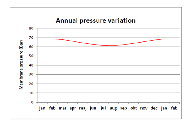
Let's take a look at a 5,000 CMD SWRO skid with isobaric ERD operating at 66 bar in a 50Hz grid and applied with an annual pressure variation of 6 bar as shown in Fig.1. The pump runs at fixed speed and is sized with 10% safety margin on the flow at maximum pressure.
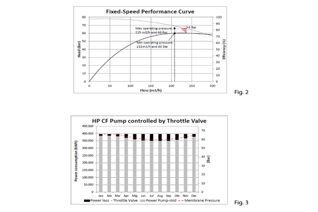
Throttling the flow in this system configuration returns the following results (see Fig. 2):
•A pressure loss of about 3 bar corresponding to 23 kWh per hour at maximum pressure in winter
•A pressure loss of about 9 bar corresponding to 69 kWh per hour at minimum pressure in summer
•Nearly constant efficiency (within 0.5%-point) with the selected pump
The results become even more explicit in Fig. 3 that shows how throttling wastes energy over the year. In fact, the total annual energy waste of the throttle valve alone is 373,000 kWh corresponding to about 8.5% of the total energy consumption of the pump. The total annual power consumption of the pump is about 4,764 MW.
Flow control with VFD on the HP feed pump
A SWRO system is characterized by high "static" pressure caused by the membrane process itself. This means that the system's pressure curve does not start from the origin but at some nonzero value on the y-axis corresponding to the osmosis pressure. Hence, the system curve does not follow the curves of constant efficiency.
When selecting a CF pump with VFD for a constant flow-regulated system, the recommendation is to select a pump that operates to the left of BEP at maximum pressure. This approach optimizes the operating efficiency of the pump. [HI]
Looking at the same 5,000 CMD SWRO plant as displayed in Fig.1 we see that choosing the pump with a safety margin of 10% of flow (3 bar on pressure), the pump efficiency is about 77.5% and nearly constant at both 60 and 66 bar and a constant flow of 215m³/h.
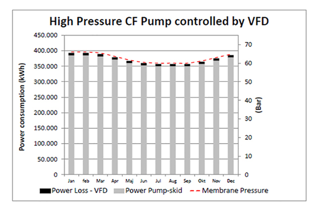
A large VFD has an efficiency rate of about 98%, and the 2% energy loss has to be taken into consideration when calculating the energy efficiency. Still, the annual power loss by the VFD is only 90.000 kWh, which corresponds to only 24% of the energy loss of the throttle valve.
Fig. 4 shows the energy consumption over the year including VFD losses. The total annual power consumption is about 4.480 MW.
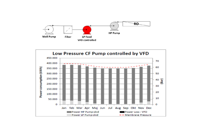
Flow control with VFD on extra LP feed pump
An alternative to use the large VFD directly on the motor of the HP CF pump is to use an additional LP feed pump with VFD control as shown in the figure below:
This LP feed pump feeds a variable pressure between 0.7-6 bar into the inlet of a constant speed HP CF feed pump, thereby compensating for the pressure variation during the year.
The drawback of this solution is that the wide pressure range may not allow a safety margin of 10%. At the same time, a plug-valve or throttle-valve may still be needed when starting the HP centrifugal pump direct online.
Some isobaric ERDs are sensitive to excess LP inlet flow, and pressure variation will typically cause flow variation. To overcome this problem, a high-quality flow-regulating valve to the ERD is needed or an individual LP feed pump with constant flow.
Looking at the same 5,000 CMD SWRO plant, Fig. 5 shows the power consumption over the year including VFD losses. The annual total Power consumption is about 4,372 MW. The power loss in the VFD is very low and may be ignored.
The VFD may be sized to only 10% of the large VFD for the HP feed pump, thereby reducing the CAPEX for the VFD, whereas further CAPEX will be added for the extra LP feed pump.
Positive displacement pumps – how does the PD pump work?
Flow regulation:
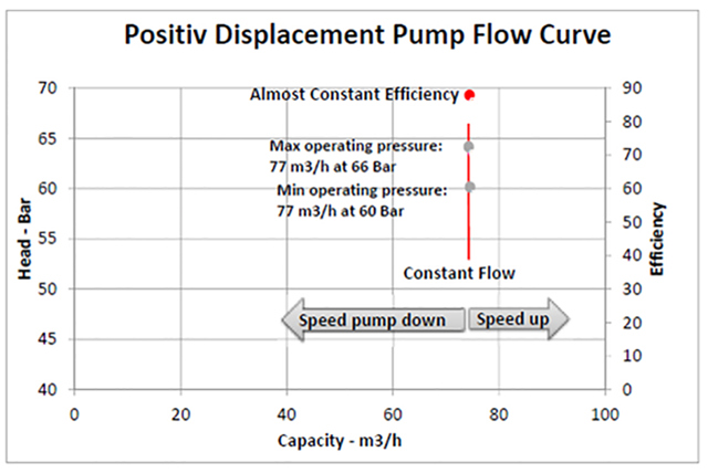
A Positive Displacement (PD) pump delivers a nearby constant flow regardless of the pressure. See Fig. 6. If the system pressure goes up, the PD pump delivers constant flow at the requested pressure without any regulation of the pump at all. Only power consumption on the electric motor goes up automatically. Similarly, if the system pressure goes down the flow remains constant and only power consumption on the electric motor goes down.
The flow from a PD pump can only be regulated by adjusting the rotation speed of the pump shaft, see Fig. 6.
The safety margin on the flow is limited to the max. flow of the individual pump.