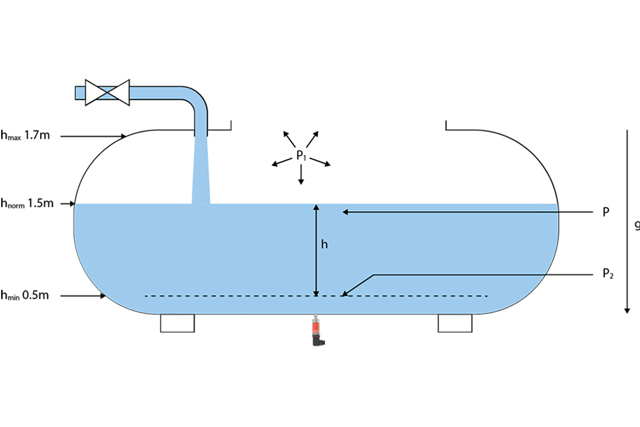
New solutions for precise and reliable level measurement

Wednesday, 2 May, 2018

Vital systems such as firefighting and water utilities rely on access to water at any time. Buffer tanks are important components in these systems and serve as local water reservoirs, ensuring that the required amount of water is present when required. 

The water tank is often a ‘black box’, and it might be difficult to determine how much water is available at a given time. Therefore, the water tank is typically equipped with some kind of level measurement device, which can provide precise measurement of the water volume.

This article explores different methods of level measurement with a special focus on the use of pressure sensors as a precise and reliable solution.

There are several ways to measure your tank’s water level, ranging from basic analogue level switches to more advanced digital pressure sensors. Among the many possibilities, hydrostatic pressure has emerged as one of the most reliable and precise methods.

The water level can be calculated by using the water density. A pressure sensor can help us to measure the hydrostatic pressure and to define the water level column. The tank geometry can be used to calculate the water volume, if necessary.

The most important prerequisite for the hydrostatic level measurement is the so-called “Hydrostatic paradox” or “pascalsches Paradoxon.” This Paradoxon describes that the pressure in the measure point in a container depends of the filling height of a fluid, independent of the filling quantity and the geometry of the container.

We are distinguishing between level measurement in open or closed container. The most important difference, between closed and open container is the influence of the ambient pressure in addition to the filling quantity of the medium in the container. This value has a big influence on the ability to get the right measurement data.

It is important to keep in mind, however, that the density can change by temperature; for instance, the water density is higher at 20°C then at 80°C. Likewise, the density of salt water is higher than demineralized water.

1. p1= ambient pressure (hPa):

The ambient pressure depends on the height of the position of the sensor application over the sea level or from the application conditions, e.g., in pressurized chambers.

The higher we are above the sea level, the lower the air pressure. For example, the ambient pressure at 0 m sea level height is 1013,25 hPa ~= 1,013 bar, while at 100m above sea level we have an ambient pressure of 1000,3 hPa ~= 1 bar.

2. ρ = density of liquid (kg/m³)

Every material has a specific density. The density is a quotient of the mass and volume of a medium. ρ=m/V 

(ρ is the density, m is the mass, and V is the volume)

The temperature has an influence on the density of a medium. The density of a medium varies with the influence of the temperature and pressure. This variation is typically small for solids and liquids, but much greater for gases.

Example density of water at 20°C & 0°C in ambient pressure:

0°C ≈ 999,8395 kg/m³

20°C ≈ 998,2071 kg/m³

3. g=   Gravity (m/s²)

Gravity is an important factor to consider in our calculation, since it has influence on all things with mass.

The standard value of gravity is 9.80665 m/s².

4. Overpressure (closed container)

Every volatile medium in an enclosed, non-ventilated container, can create overpressure above the fluid. This overpressure cannot be compensated with ambient pressure due to lack of ventilation.

Let’s say that one of our customers needs a solution for level measurement in the open cooling water container in their new plant. The water container has a Ø of 890 mm and a height of 2500 mm. The normal water level will be 1500 mm and the minimum water level will be 500 mm. At 1700 mm max water level, an alarm signal is needed to alert employees to cut the water supply in the tank so that it does not overflow.

The ambient temp will be between 8 °C and 35 °C. The Medium temperature will be 10 °C to 25 °C. The medium is water.

The customer requests a sensor with a 4 to 20 mA output and accuracy better than 2% on the measuring range of the sensor. The process connection and other parameters (electrical plug) are flexible.

The sensor will be installed in the bottom of the tank to measure the water column.

The first step is to select all the mentioned data and calculate the max pressure of the media in the mentioned application:

Container type:

open (vented tank) ambient pressure influence
p1 ambient pressure= 1000,3 hPa ~= 1 bar
p2 Hydrostatic Pressure =?
h height of the tank= 2500 mm=2,5m
ρ water density at 10°C = 999,70 kg/m³
hmax water column= 1700 mm =1,7 m
hnorm water column= 1500 mm =1,5 m
hmin water column= 500 mm =0,5 m
Ø container= 890 mm = 0,89 m
V container volume=(π*d²)/4 h = (3,14*0,89m²)/4*1,7m=1,19m³
A container surface=π*d*H =3,14*0,89m*2,5m=6,98m²


With the tank volume value, we know that the max level of water in the tank will be 1,19 m³ or 1190 l. We also know that water has a density of 999,70 kg/m³ or ≈1kg /l .
That means that the max weight of the water in the container will be approximately 1190 kg.
To calculate the pressure in the bottom of the container, we need only the ρ (water density), g gravity, and max height of the water column. The container surface and volume are not so relevant.

Calculation:
P2= ρ⋅g⋅hmax=999,70kg/m^3 *9,81m/s^2 *1,70m=16672kg/m*S²16.672 kg/m*S² or Pa (pascal) (16672 Pa =167 mbar)

With this knowledge we can select an additional sensor for the application.
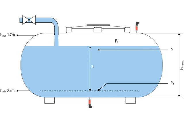
For open tanks, it is important to use a relative sensor to compensate for the influence of the ambient pressure. With a relative sensor (vented sensor), the ambient pressure will not have an influence on the measurement.

The MBS 9200 sensor with the code no. 064G523 is a relative sensor with 0 to 0,2 bar (200 mbar) pressure range, 4 to 20 mA output signal and accuracy TEB +- 1,5%.

The pressure range is a little higher than necessary, but this has no negative impact on the measurement.

The signal table could look like this:

Sensor Output(mA) h water column (cm) mbar function
4 0 0 Empty Container
8 50 50,9 Level 1 min
12 100 101,8 Level 2
16 150 152,7 Container full
17,6 170 173,06 Alarm - Valve cut off

For a closed container, the important parameters are the same as for an open container. The only difference is that most of the closed containers are pressurized and don’t have a vented connection to the ambient pressure. To compensate for this value, it makes sense to install another sensor at the top of the container.

If the container is vented, we must considerate the influence of the ambient pressure in the calculation.

Application example:

If we have in a closed container (no ventilation) with a medium that evaporates, such as gasoline, we will get an overpressure above the liquid. This overpressure will sit in the top of the tank and can be changed without influencing the medium level. This overpressure must be measured by another pressure sensor, as the gas trapped above the liquid causes a higher hydrostatic pressure, which must be compensated for to avoid false values on the level measurement.

Container type: 

closed (no vented tank) overpressure influence

p1 overpressure= 80 hPa ~= 80 mbar
p2 hydrostatic Pressure=150 hPa = 150 mbar
htank height of the tank= 2500 mm
ρ Gasoline = 750 kg/m³

We want to know the real medium level on the container. For this calculation, we can use the following formula:

h medium column=((p2-p1) )/((p*g))= ((150 mbar-80mbar))/((750kg/m^3 *9,81ms/s^2 ))=70mbar/(7357,5 kg/m*S²)=70mbar/73,5mbar=0,95m

If we decide to make the same calculation with estimated medium values based on the typical prevailing gas pressure, you will get a miscalculation of the filling level. This could lead to a critical error in the application process.
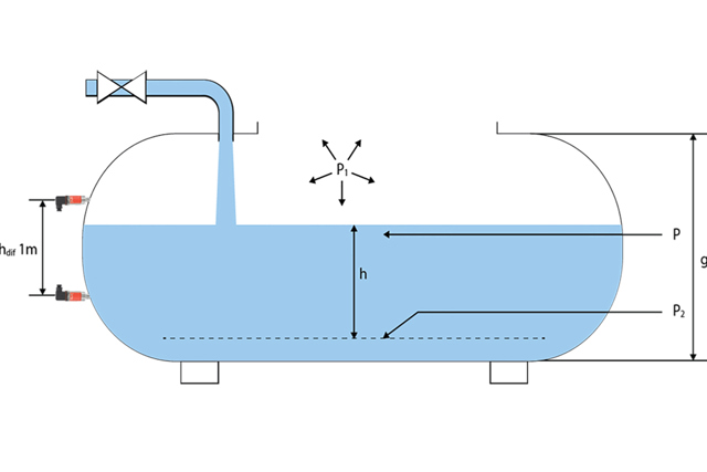
Another typical sensor application in an open or closed container is to define the unknown or alternate media density using differential pressure. This can be realized if we mount two sensors at two different points in the medium column of the container. It is important to know the exact distance between the sensors to accurately calculate the media density.

Container type:

open

p1 overpressure= 6864,93 kg/m*S²=6864,93 Pa
p2 pressure=16672kg/m*S²=16672 Pa
ρ density = ?
g gravity = 9,81 ms/s²
hmax medium column= 1700 mm =1,7 m
hdif difference between 2 sensors=1m

Ƥ=((p2-p1))/((hdif*g))=((16672 kg/m*S2-6864,93 kg/m*S^2))/((1m*9,81 m/S²))=(9807,07 kg/m*S²)/(9,81 m/S²)=999,70 kg/m³

We can say now that the medium in the container has a density of 999,70 kg/m³. This is equal to the water density at 21°C.

If density change is caused by temperature, a temperature sensor can be installed.

The pressure sensor is more precise when calculating the water level than a traditional multi-level switch. This precision is critical if the tank has a large surface area, where a slight water level miscalculation could hide the fact that several cubic meters of water are missing in the tank.

The precision of the pressure sensor allows for optimization of the water tank layout, i.e. using a flat tank with a large surface area, while gaining peace of mind that the required water volumes will be available when needed. 

High reliability and cost savings during operation

The highly reliable precision sensors are easy to mount and save costs during installation. The sensors also provide additional advantages in terms of cost savings and reliability.

First, the fast response time of the pressure sensor enables real-time measurements for control of the tank’s water level. The sensor sends alarms if anything unusual is detected, which allows operators to identify and repair leaks or other system faults immediately.

The pressure sensor also provides long-term stability and, therefore, reliable measurements over the service life.

The pressure sensor can be used with a wide range of media. Unlike other level measurement technologies, the pressure sensor protects against false measurements with changes in viscosity or contaminants in the water.

Water level pressure sensors from Danfoss: MBS 9200 and 9300

  • Multi-purpose, low pressure, digital sensors
  • Type 9200 for general, industrial applications; Type 9300 for marine applications
  • Compact and lightweight for flexible use in different designs
  • Pressure range from 20 to 250 mbar
    Offer self-diagnostics and automatic alarms
  • Enclosure and wetted parts of stainless steel (AISI 316L)