Transcritical CO2 systems has taken large market shares the last years, and based on the view point of the politicians and the public opinion, the decision makers around the world has been increasingly focussed on utilising CO2 as a primary Refrigerant.
Chapter 1. Transcritical CO₂ refrigeration with heat reclaim
Transcritical CO₂ systems has taken large market shares the last years, and based on the view point of the politicians and the public opinion, the decision makers around the world has been increasingly focussed on utilising CO₂ as a primary Refrigerant.
This increasing focus makes it much more interesting from the view point of the refrigeration plant builders to exploit the possibilities within CO₂ The refrigerant CO₂ shows extremely good possibilities of reclaiming the heat from the systems. The technology used in the transcritical systems is relatively new but is evolving rapidly, and is now of a degree of maturity, that now reveals the real opportunities for utilising heat reclaim. Especially the mature packs, primarily developed in the Nordic countries, now provides simple and reliable ways of designing transcritical heat reclaim systems, which at their best, can provide the entire installation with ALL necessary heat. The nature of the transcritical technology opens up for new ways of doing things. The capacity from the heat reclaim can be varied from 0 - 100 % of the capacity, but it also opens the door for a higher energy consumption if things are not done correct.
The main objective for a heat reclaim system must be to reclaim the heat needed, at the needed temperature as efficient as possible.
In this article there will be given a brief description of the system design and control strategy.
Chapter 2. System design
In general all heat exchangers are placed in series to optimize the COP of the system by ensuring the lowest temperature out of the gas cooler. There can be placed as many heat exchangers as needed in series, but on most systems one or two heat exchangers for heat reclaim and one air cooled gas cooler will be the most common. For the purpose of providing hot tap water, it will be a good idea to make a system with two heat exchangers, since this will ensure the highest efficiency on the system. The disadvantage of cause will be higher initial cost, but in many cases a payback analysis will show when this will be the best solution. In this article there will be one heat exchanger for heat reclaim and one air cooled gas, but the control strategy will be the same if more heat exchangers are needed.
From the compressor the hot gas enters the first 3-way valve. In heat reclaim mode the gas will go to the heat reclaim heat exchanger. In the heat reclaim heat exchanger the gas is cooled down to as low temperature as possible. The most common heat exchanger for heat reclaim is tube in tube or plate heat exchangers. From the heat exchanger the cold gas goes through the second 3-way valve. This valve directs the gas through the air cooled gas cooler or bypass it directly to the high pressure expansion valve. In the gas cooler the gas is cooled further down before it enters the high pressure expansion valve.
This is the basic setup. There can be many variations of it, but this is the most common and most widely used.
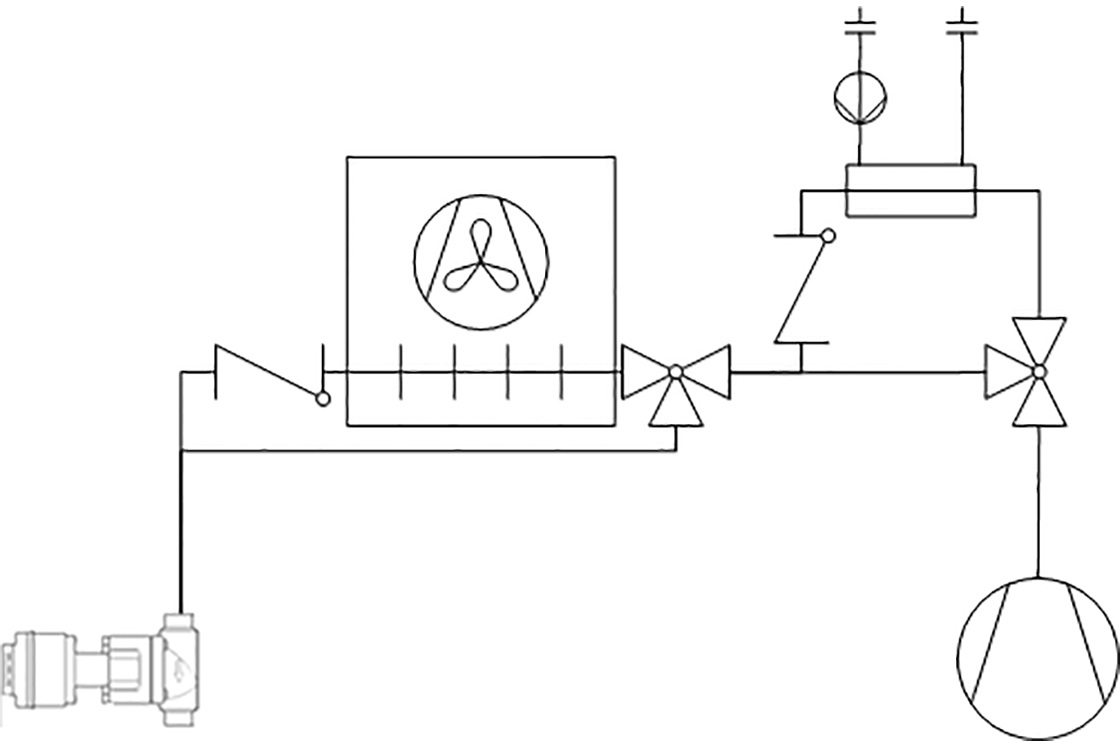
Figure 1: Basic system design for transcritical heat reclaim system
Chapter 3. Control strategy
To meet the objective of reclaiming the heat needed, at the needed temperature as efficient as possible, the control strategy needs to cope with this.
There are the following measures that can be used to do this.
- Pump speed on the secondary side
- Fan speed on the gas cooler
- High pressure
- By pass of gas cooler
The important thing is to use these measures in the right way to optimize the output of the system.
The Danfoss strategy is to do this in 5+1 steps. The heat load on the heating system is fed back to the controller from the building management system or from a PI controller.
In the following description small examples are included. The basic data for the examples are:
- Ambient temperature 0 °C
- Water inlet temperature 25 °C
- Water outlet temperature 65 °C
- Exit temperature difference air cooled gas cooler subcritical 8 K
- Exit temperature difference air cooled gas cooler transcritical 2 K
- Exit temperature difference heat reclaim heat exchanger 5 K
Chapter 4. Step 0
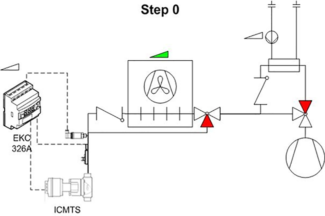
Figure 2: Diagram Step 0. Normal refrigeration
Step 0 is normal cooling without any heat reclaim. If something goes wrong step 0 will be used as fail safe mode to avoid loss of goods. Cooling is always first priority.
Example
![]()
In Step 0 the mode is cooling only and therefore the high pressure is as low as possible. In this case the high pressure is optimized to 8 °C. No heat is reclaimed.
Chapter 5. Step 1
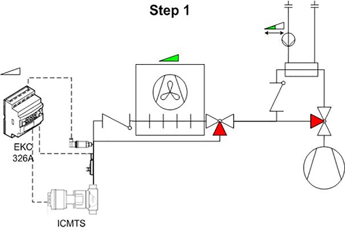
Figure 3: Diagram step 1
In step 1 the pump is turned on. There is different ways to control the pump speed, but normally the speed is controlled to maintain a fixed temperature out of the heat exchanger, but temperature difference of the water or in going water temperature can also be used. All of them makes sense in different systems. When the pump is at minimum speed and the flow switch in the water circuit is on and the temperature in the water circuit is below 95 °C the 3 way valve is turned. The pump speed is adjusted so the temperature set point is satisfied.
This will remove the part of the supper heat with the highest temperature.
If this is not enough to satisfy the heat load the controller will be forced in to step 2
Example
![]()
In the example the pump is running, but the discharge temperature in not high enough to satisfy the required temperature and therefore the system rapidly will go to Step 2. If the ambient temperature had been higher the discharge pressure and therefore also the discharge temperature would have been higher and therefore there would have been some heat to reclaim.
Chapter 6. Step 2
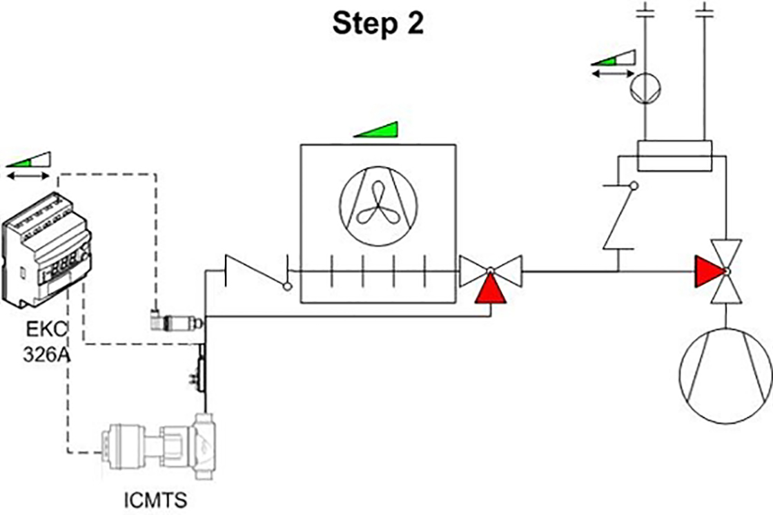
Figure 4; Diagram step 2
In step 2 the pump is still running according to the temperature, but the high pressure is pushed up to make a bigger part of the heat available at the temperature needed. This is done by changing the set point in the high pressure controller and thereby closing the high pressure expansion valve. The higher pressure increases the compressor work but also gives a very large increase in the heating capacity and therefore it makes good sense.
In step 2 the heat rejection in the air cooled gas cooler is still a big part of the total heat rejection of the system. Since it is not possible to increase the pressure more, or maybe it is not efficient to raise it higher, the heat rejection has to be limited to get more heating capacity out of the system.
Example
![]()
By increasing the pressure the part of the heat rejection that can be reclaimed is increasing and at the same time the discharge temperature is increasing. At approx 85 bar (in this example) it is not efficient to raise the pressure higher. The compressor work would be too high and the reclaimed heat is not increasing at the same rate.
Chapter 7. Step 3
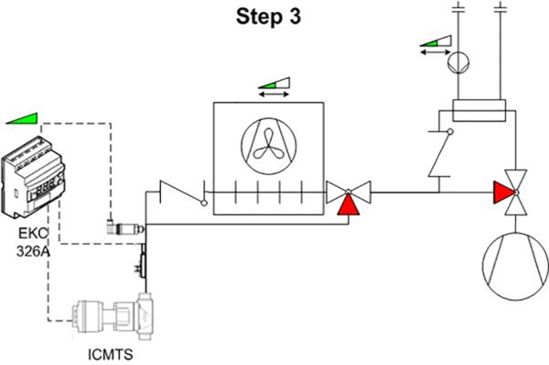
Figure 5: Diagram step 3
In step 3 the set point for the fans is gradually pushed up until the fans are stopped. This makes the heat rejection from the air cooled gas cooler decrease. This will result in a loss of cooling capacity, but the system will compensate by putting in more compressor capacity. This will also result in a higher compressor work, but also more capacity on the heat reclaim system.
Even when the fans are stopped the natural convection of the gas cooler is enough to take some capacity out of the system.
Example
![]()
By reducing the condenser fan speed the capacity is reduced. Therefore the part of the heat reclaimed is increasing, and the part rejected to the ambient is decreasing.
Chapter 8. Step 4
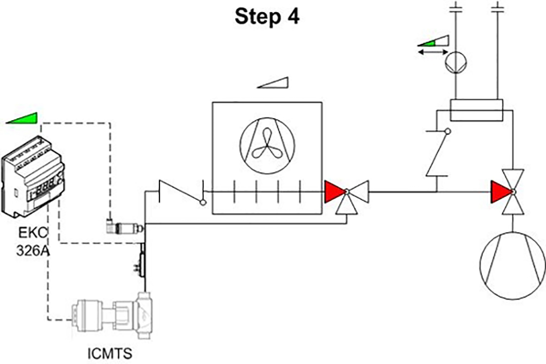
Figure 6: Diagram step 4
In step 4 the air cooled gas cooler is bypassed to avoid natural convection and there by heat rejection from this part of the system. As in step no 3 this reduced the cooling capacity, but the system will compensate by putting in more compressor capacity. This will also result in a higher compressor work, but also more capacity on the heat reclaim system.
At this point no heat is rejected to the ambient and the system is basically running as a heat pump system but with the control sensor on the low temperature side.
Example
![]()
By bypassing the gas cooler all heat rejected from the system has to go in to the heat reclaim system.
Chapter 9. Step 5
In step 4 all heat put in to the system is reclaimed. If the heating demand is still not satisfied the load on the cold side of the system has to be higher. This can be done by adding an extra evaporator that takes heat from the ambient - the efficiency of this is lower than the other steps, but makes an easy solution on getting more heat. The efficiency should be looked at on a yearly basis, because the number of hours running in step 5 should be taken in to account.
Example
![]()
The Log P-h diagram is the same as in step 4 because it is only the mass flow of the system that is changed by adding more capacity on the evaporator side.
Chapter 10. Features and Challenges
Heat reclaim in a transcritical system is not trivial and the experience is limited. There are things that are different from conventional systems, but they only need to be addressed and handled.
Condensing in the heat reclaim heat exchanger
Since it is possible to do a partly reclaim the CO2 can be partially condensed in the heat reclaim heat exchanger. When using more than one heat exchanger, the problems grow accordingly, and the strategy becomes slightly more complex to prevent the different problems that may occur. One problem that may occur, is that the liquid can build up in one part of the system, and then, due to the gas pressure, shoot out into the system at high velocity, and maybe severely damage parts of the system.
This problem can be handled in many ways.
- The system can be forced in to transcritical mode when there is a need for heat reclaim. This will reduce the efficiency of the system, but the operation is safe because there is only one phase.
- The inlet water temperature can be kept high enough (maybe 30 °C) to ensure it is not possible to condense. This will not force the system to run transcritical but still reduce the efficiency. This control strategy can be made with a mixing loop on the water side.
- The pressure in the system can be controlled in a way so the super heat out of the heat reclaim heat exchanger it kept high enough to insure condensation is not taking place. This is a safe and the most efficient way to control the process.
- Secure that the temperature between various heat exchangers is in an appropriate level.
In some system designs condensations is not a problem, but this needs to be taken into consideration in the system design.
Charge variations
Another issue that needs to be addressed is variations of the charge. The average density of the CO₂ in the gas cooler varies roughly by a factor of 2 under different conditions. By introducing heat reclaim to the system this problem in increasing dramatically. But removing the heat in the heat reclaim system the density of the refrigeration gas is increasing before the air cooled gas cooler and this makes the mass in the air cooled gas cooler go up! Therefore the internal volume of the air cooled gas cooler has to be reduced to a minimum without compromising the performance of the system. This can be done by choosing small diameter tubes in the gas cooler.
Conclusion
Heat reclaim in a transcritical system is a very attractive alternative to HFC solutions. The efficiency is higher and the temperatures that can be obtained are higher comparing to HFC technology. The technology to do an optimised heat reclaim is in the market at the moment and there are several installations running in the Nordic countries. Out of these installations, it has be shown, that it is possible for correct designed systems, where the heat demand is not high, to eliminate additional heat sources. This makes heat reclaim a very interesting subject when looking at total costs.