This issue is dedicated to main valves, which are used primarily in relatively large commercial and industrial refrigeration systems. They are extremely versatile and can be used for a wide variety of purposes. For example, they can be used to regulate evaporating pressure, condensing pressure, differential pressure, crankcase pressure, capacity, and much more depending on which pilot valve is fitted.
This issue is dedicated to main valves, which are used primarily in relatively large commercial and industrial refrigeration systems. They are extremely versatile and can be used for a wide variety of purposes. For example, they can be used to regulate evaporating pressure, condensing pressure, differential pressure, crankcase pressure, capacity, and much more - depending on which pilot valve is fitted.
In this installment we discuss the configuration and specific use of ICS main valves as an example. This also applies to PM main valves, which have exactly the same pilot ports and connections as ICS valves.
ICS main valves are available in one-pilot and three-pilot versions. With the one-pilot version, a single pilot valve can be screwed directly onto the main valve, while the three-pilot version allows up to three pilot valves to be fitted to the main valve. The one-pilot version can be used to regulate a single function, such as evaporating pressure or condensing pressure.
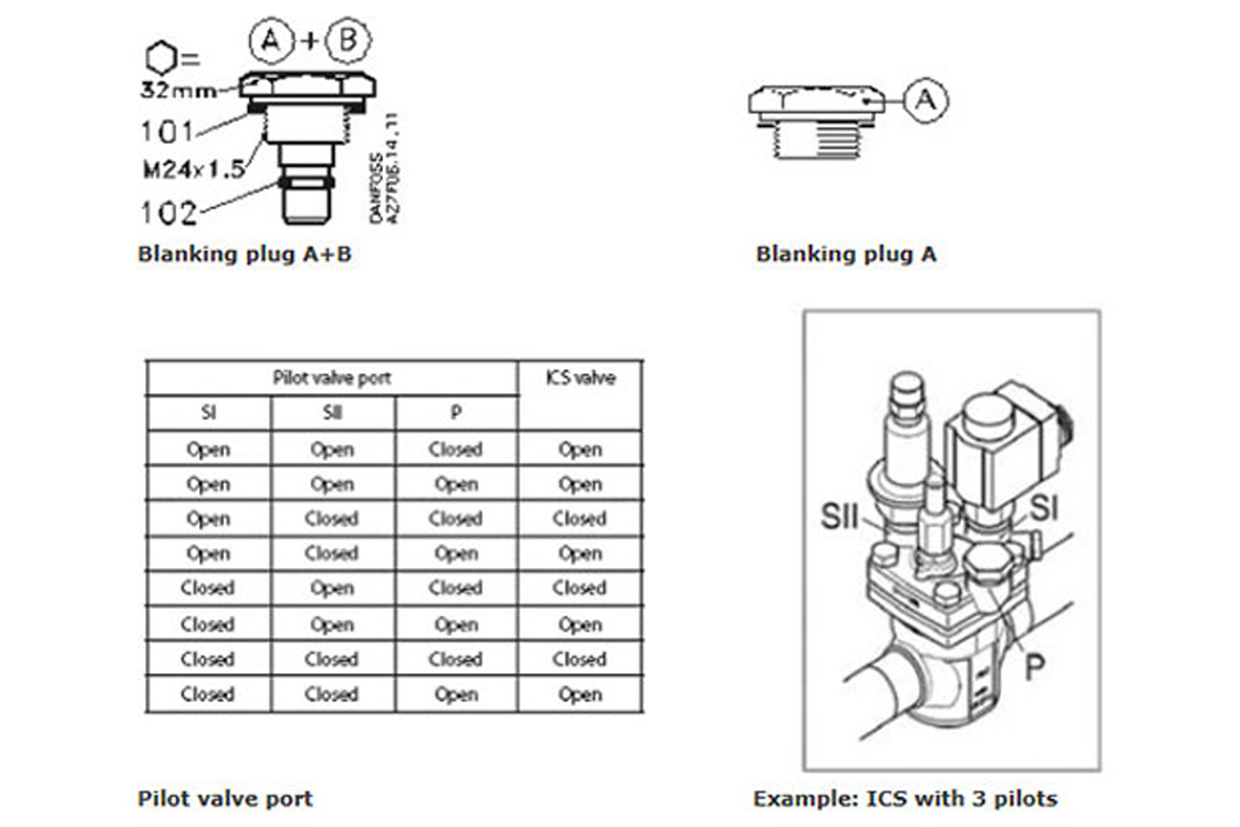
Three-pilot ICS valves can do much more. They have two pilot ports that are connected in series, along with another pilot port that is connected in parallel with the other two. The ports connected in series are marked "S1" and "S2", where "S" stands for "series". The parallel port is marked "P" and is arranged in parallel with the S1 and S2 ports. This enables configuration options such as condensing pressure regulation with supplementary forced opening or forced closing. If the number of pilot ports is not sufficient to meet the needs of an especially complex configuration, external pilot housings and pilot valves in external pilot lines mounted on these housings can be used to implement an almost endless number of configuration options.
To simplify system commissioning, ICS main valves also provide the capability of manual forced opening. The main valve can be opened manually using the manual spindle located in the middle of the valve head. For normal operation, this manual valve spindle should always be turned back to its initial position (anti-clockwise until it reaches the stop).
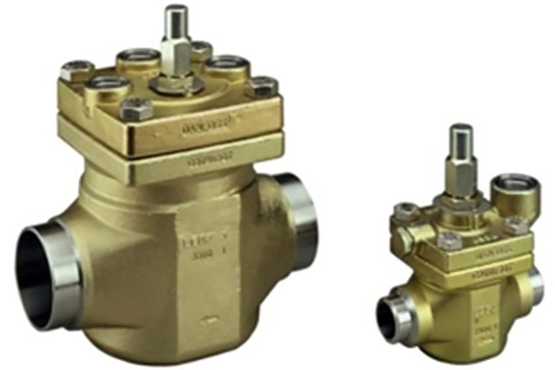
An ICS main valve has a basic housing body that is soldered directly to the pipe (or welded if ammonia is used as a refrigerant). A function module is fitted in this basic body, so that it can easily be replaced when service is required without affecting the pipe connections.
When configuring main valves, you must bear in mind that they are servo valves that require a certain minimum pressure drop. Although this pressure drop is very small, which allows very good partial-load capability, it cannot be neglected. If the application (such as a freezer application) actually requires a valve with no minimum pressure drop, this can be achieved with the ICS valve by using a higher pressure to operate the valve. An external pilot connection can be fitted to the ICS valve for this purpose. The valve, which is fitted in the suction line, is opened by the hot gas or cold gas pressure fed to it by a small pipe. The configuration for this consists of an ICS valve (three-pilot version) with an external connection to S1, an EVM connected to S2, and an A+B plug in P. Alternatively, a type PML(X) can be used as a special main valve for this particular application.
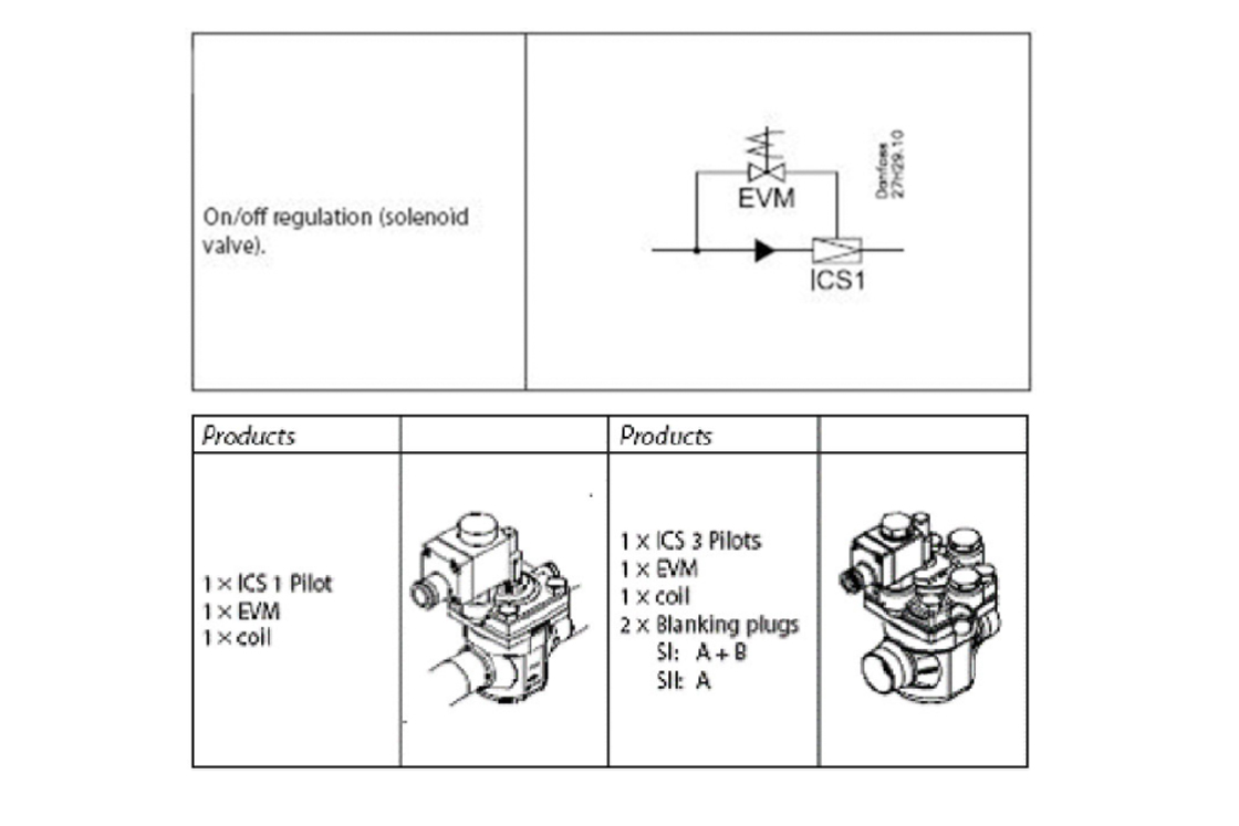
The simplest use of a main valve is as a solenoid valve. For this purpose, the one-pilot version of the main valve is equipped with an EVM pilot valve. This pilot valve can be screwed directly to the main valve. Solenoid valves are most often used in normally closed (NC) mode, which means that the valve is closed when the solenoid is not energised. The NC version of the EVM pilot valve is suitable for this purpose.
When the coil of the EVM (NC) pilot valve is energised, the pilot valve opens. This in turn opens the internal control channel in the ICS valve between the valve inlet and the internal pressure chamber above the power piston, so that high-pressure gas flows from the valve inlet into the pressure chamber above the power piston and presses the piston downward. This causes the main valve to open.
To close the main valve, the channel is closed by the EVM valve and the high pressure on the power piston is vented to the valve outlet via a small drilled hole. An EVM (NO) valve can be used for operation in the opposite mode ("NO" stands for "normally open", which means that the valve is open when it is not energized). In addition to the different operating sense, EVM (NO) pilot valves differ from EVM (NC) pilot valves in two ways: they are fitted with a slightly stronger coil (12 W for AC use) and they have an additional nut pressed into the lower part of the anchor tube.
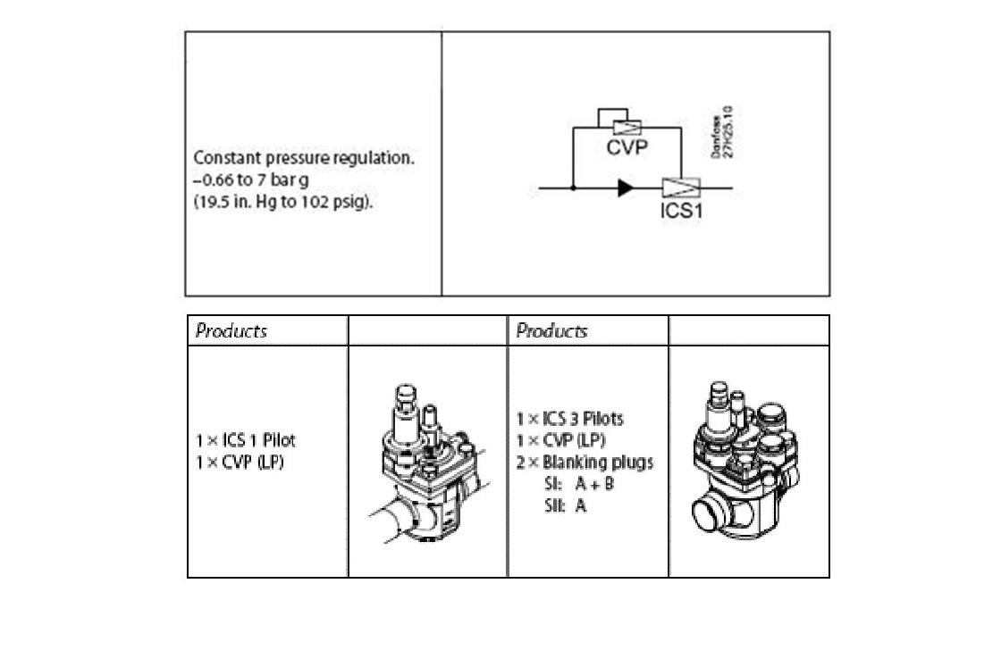
Evaporating pressure regulators are fitted after evaporators (such as in a multi-evaporator system) that must be operated at a higher pressure than other evaporators on the same circuit. Evaporating pressure regulators are also often fitted to chiller units to provide additional protection against freezing of the water in the evaporator.
A main valve fitted with a type CVP 7 pilot valve can be used as an evaporating pressure regulator in relatively high-capacity systems. The best way to adjust the set-point pressure - below which the valve closes and above which it allows refrigerant to pass through (valve open) - is to use two low-pressure gauges. One of the gauges is connected to the suction connection of the compressor, while the other is used to display the pressure between the evaporator and the evaporating pressure regulator. The second gauge can be connected to the service port of the ICS valve, since the inlet pressure of the valve can be read at the measuring port on the gauge connection. After this, the set-point value can be adjusted directly at the CVP. Turning the adjustment clockwise (in the + direction) increases the set-point pressure, while turning it anti-clockwise (in the - direction) reduces the set-point pressure. If the pressure drop increases when the setting is adjusted while the system is operating, it is sufficient to set the regulator to the desired regulator input pressure.
If you have only one low-pressure gauge available for measuring the evaporating pressure and increasing the set-point value to the desired value while the system is operating results in a correspondingly higher evaporating pressure, the regulator is adjusted correctly. Caution is necessary if the actual evaporating pressure is higher than the desired set-point value. Here it is not possible to directly adjust the setting without first taking other actions, since the regulator will always be open for any set-point value below the actual value. In such a situation, the evaporating pressure must first be reduced. For example, this can be done with a fan-cooled evaporator by switching off the fans. The fans should be switched back on after the CVP has been set. Main valves can also be used for switching between two different evaporating temperatures. For example, with a three-pilot main valve equipped with an EVM pilot valve and two CVP pilots set to two different evaporating temperature levels, you can switch between two different evaporating pressures by energising or de-energising the EVM valve.
Condensing pressure regulators are used to prevent the condensing temperature from dropping too low in a refrigeration system, especially during cold weather. They can be fitted in the hot-gas line downstream of the T-fitting branch to the receiver pressure regulator or in the condensate line. A check valve must always be fitted in the condensate line if the regulator is fitted in the hot-gas line, as otherwise refrigerant could flow back into the cold condenser and the desired effect of a rapid pressure decrease before the expansion valve would no longer be assured during winter start-up.
The most commonly used option is to fit the condensing pressure regulator in the condensate line (between the condenser and the receiver). A condensing pressure regulator for a high-capacity system is almost the same as an evaporating pressure regulator. It consists of an ICS (or PM) main valve with an attached pilot valve (type CVP 28 or CVP 22 for R134a). The number after "CVP" stands for the maximum control pressure of the pilot valve, in this case 28 bar or 22 bar.
It is hardly surprising that the components necessary for evaporating pressure and condensing pressure regulators are similar, since in both cases the objective is to define a certain minimum pressure that must be maintained. The two applications differ only in the overall pressure level. To adjust the setting, you should at least connect a high-pressure gauge to the gauge port of the ICS valve (a gauge port adapter for ICS valves is available as an accessory and can be retrofitted as necessary).
The best results can be obtained by connecting an additional high-pressure gauge to the receiver. The rest of the procedure is the same as for the CVP evaporating pressure regulator. The ideal situation is when a condensing temperature distinctly lower than the desired set-point value is obtained when the system is operating with a "relaxed" CVP (very low setpoint value). If the pressure (with one high-pressure gauge) or the pressure drop (with two high-pressure gauges) increases significantly when the set-point is adjusted to a higher value, you can set the desired set-point value directly. If the pressure on the high-pressure side is too high (for example, during a period of especially warm weather), you can postpone system commissioning to a cooler time. Another option, which for example can be used with a multi-compressor system, is to operate the system with only one compressor while the condensing pressure regulator is being adjusted.
In difficult cases, it may also be helpful to reduce the pressure level on the low-pressure side, as described in the "Evaporating pressure regulation" section. Generally speaking, this will also reduce the pressure on the high-pressure side. Here it is also possible to implement switching between two different condensing temperatures, in the same way as for the evaporating pressure. This can be done using a three-pilot main valve, two CVPs set to different condensing temperatures, and an EVM pilot valve.
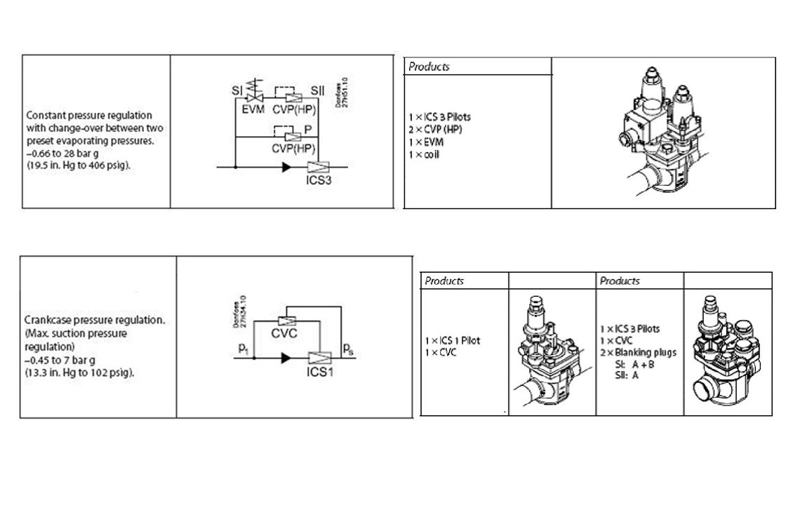
A crankcase pressure regulator is desirable if the system compressor (often a freezer compressor) must be protected against excessively high pressure. The regulator is fitted in the suction line. Crankcase pressure regulators have fallen somewhat out of fashion in recent times with the use of individually (electronically) adjustable MOP points in systems with electronic injection control. Nevertheless, they still hold their own as traditional pressure regulators.
For larger systems, it is recommended to use an ICS (or PM) main valve with a CVC pilot valve. A branch line must also be routed to the CVC pilot valve from the main line downstream of the main valve. This feeds the actual value of the pressure to be regulated between the valve and the compressor to the crankcase pressure regulator. Adjusting a crankcase pressure regulator is easy while the system is operating if the evaporating temperature is higher than the desired set-point value.
The CVC does not need a separate measuring port, since a measuring port is usually available on the compressor suction stub. This measuring port can be used for the adjustment. Here again the procedure is similar to the procedure for the CVP options, but in the opposite sense. This means that if it is possible to directly reduce the suction pressure ahead of the compressor and set it to the desired set-point value by actuating the CVC, the device is functioning properly. This can be seen even better if a second low-pressure gauge is used, for example connected to the evaporator outlet. Here you can clearly see that no pressure drop would occur without the CVC, and that the pressure drop matches the desired set-point value when the value is properly adjusted.
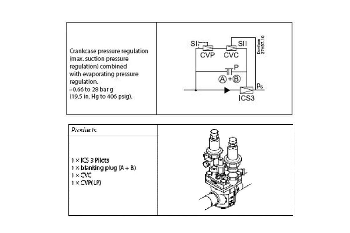
The only situation that makes crankcase pressure regulator adjustment difficult is very low suction pressure, but there is an easy solution to this problem. This situation usually occurs with freezer systems, which means that defrost heating can be used to increase the suction pressure. Another option is to set the freezer cell temperature to a higher value than the normal operating point. This is usually not difficult during construction. Combinations of several functions can be implemented using a main valve. For example, you can combine crankcase pressure regulation with evaporating pressure regulation by connecting CVP and CVC pilot valves in series to the S1 and S2 ports of the main valve. With this arrangement, the evaporating pressure is held constant and exceeding the maximum suction pressure is also prevented.
Capacity regulators are often used in systems where automatic capacity adjustment is necessary during partial-load operation. This is based on the principle that the suction pressure drops when the amount of heat entering the evaporator is less than under full load. This means that the set-point value of a hot-gas bypass system is set slightly lower than the suction pressure at full load under stable operating conditions. If the suction pressure decreases, the relationship between compressor and evaporator cooling capacities shifts in favour of the compressor, and the capacity regulator opens and allows hot gas to flow from the high-pressure side to the low-pressure side. This prevents any further drop in the suction pressure. The investment cost of such a solution is low compared with a compressor pack solution. In the latter case, suction pressure stabilization is achieved by switching compressors on and off. A disadvantage of the hot-gas bypass control arrangement is its energy consumption.
There are two sorts of hot-gas bypass regulators in terms of their operating principle. In single evaporator systems, the bypass regulator is located in the injection line (between the expansion valve and the evaporator), while in multi evaporator systems, hot-gas regulation is applied to the suction line. Most systems of the latter type are equipped with reinjection for chilling the refrigerant. For larger capacities, an ICS (or PMC) main valve fitted with CVC pilot valve is the right choice for both applications. A low-pressure gauge is necessary for adjusting the hot-gas bypass regulator. An evaporating pressure below the set-point value is ideal for adjusting the setting. In this case, the bypass regulator can be adjusted directly to the desired value. The flow noise provides a clear indication of whether bypass is occurring.
If the evaporating pressure is too high, the same measure as described under 'Evaporating pressure regulation' must be taken. There are also conventional injection valves for de-superheating available that are designed to have the sensor fitted on the pressure side of the compressor. However, it is also possible to use a normal expansion valve with internal pressure equalisation as an injection valve for de-superheating. For this purpose, it is only necessary to adjust the superheating setting to a higher level and fit the sensor on the suction side ahead of the compressor. A practical rule of thumb is 15 K. This prevents the injection valve from interfering with the normal injection valve, while still ensuring that the intake temperature at the compressor does not rise too high.
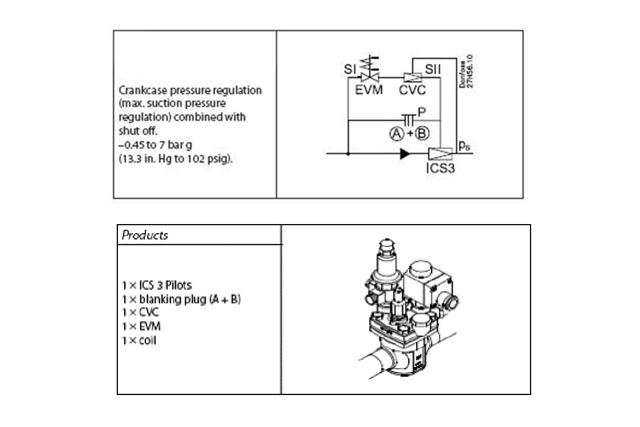
Forced closure is a very effective feature with a capacity controller. This can be implemented with just one ICS valve by fitting an EVM pilot valve in series with a CVC pilot valve (with these two pilot valves connected to the S1 and S2 ports) and closing the P port with a plug. Plugs are available in two versions: version A, which only closes the outward connection, and version A+B, which also closes the internal channels.
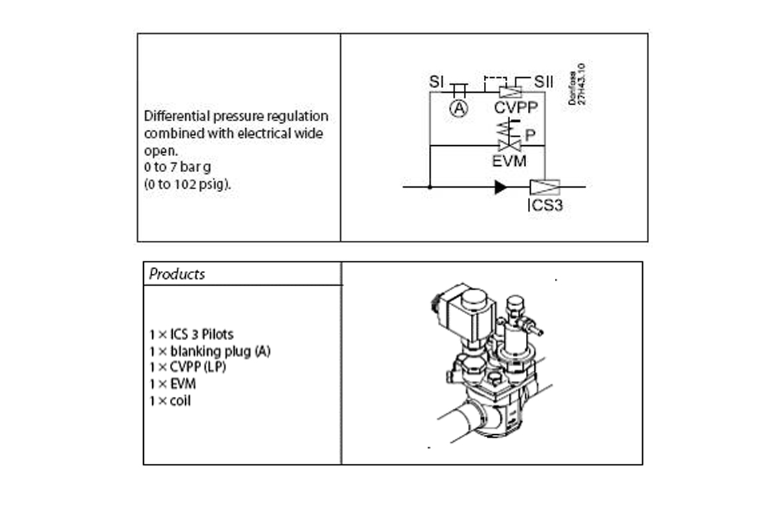
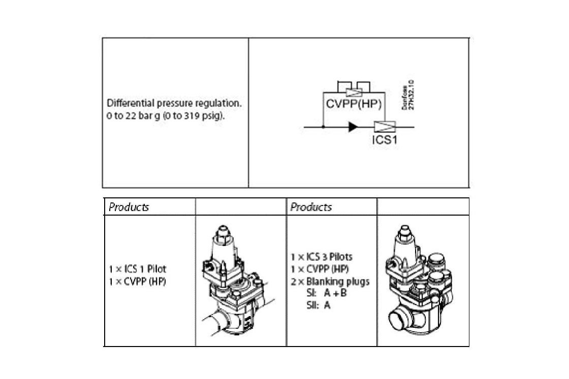
Receiver pressure regulation is normally used in combination with condensing pressure regulation. A receiver pressure regulator is necessary for bypassing the condenser for system start-up in the winter and blocking the bypass when the normal operating state has been reached. This arrangement ensures a rapid pressure increase ahead of the expansion valve, even with low outdoor temperatures, and avoids undesired system shutdowns triggered by the low-pressure control. For high-capacity systems, Danfoss (www.danfoss.com) offers ICS (or PM) main valves fitted with a CVPP differential pressure pilot valve. The ICS/CVPP combination provides regulation based on the differential pressure, which can be adjusted as desired. The best time to adjust the CVPP to the proper setting is during winter operation. For this purpose, first start up the refrigeration system and then wait until the pressure has built up on the high-pressure side. The condensing pressure regulator is still closed. The difference between the high pressure and the receiver pressure is high during start-up. As a result, the refrigerant flows through the bypass to the receiver. A practical rule of thumb is to set the CVPP to 1.5 bar. This value can be increased as necessary by clockwise rotation.
Besides receiver pressure regulation, there is also another application for differential pressure regulation. This involves systems with hot-gas defrosting, because in such systems the hot gas must flow through the evaporator toward the liquid line during defrosting. It must also be possible to disable this artificial differential pressure when the system is not operating in defrost mode. In this case, it is recommended to use an ICS (or PM) main valve fitted with a CVPP differential pilot valve, as previously mentioned. In order to disable differential pressure regulation, which is not necessary for operation in receiver regulation mode, an additional pilot valve is necessary: an EVM solenoid valve for direct fitting to the ICS (or PM). If the two pilot valves - CVPP (don't forget the branch line to the main line downstream of the valve) and EVM - are fitted to an ICS designed for a maximum of three pilot valves, the differential pressure function of the CVPP will be active when the EVM is closed. When the EVM is open, operation with (elevated) differential pressure is disabled.
The EVM solenoid valve must be closed for adjusting an ICS main valve fitted with CVPP and EVM valves.
Here you must be careful, because these pilot valves are available in two versions: closed when de-energised and open when de-energised. For example, a EVM that is closed when de-energised (type NC) is closed when no power is applied to the coil. When the solenoid valve is closed, the differential pressure can be adjusted directly while the system is operating after two high-pressure gauges have been connected ahead of and after the control valve. The compressor outlet stub can be used as the measuring point on the upstream side of the valve, or better yet, the gauge port on the side of the ICS valve (which is always at the valve inlet pressure). A measuring point on the condenser or receiver can be used on the downstream side of the valve, or a suitable T-nipple on the branch line to the CVPP can be used.