4.1 Vibration level monitoring
Many mechanical failures, e.g. bearing wear-out, shaft misalignment, unbalances, create some kind of vibration. Thus, vibration monitoring has been established as state of the art for monitoring rotating machines. There are various methods ranging from basic simple monitoring up to highly sophisticated monitoring [3]. A widely used method is vibration velocity RMS monitoring [2]. It is based on the RMS value of the vibration signal that is measured through a vibration sensor. Many mechanical faults have a significant impact on the RMS of the vibration, e.g. unbalances, shaft misalignment, and looseness. However, the challenge in variable speed applications is the dependency of the vibration on the actual speed. Mechanical resonances are typical examples. These are always present, and a monitoring system has to cope with them in some way. Often the fault detection levels are being set for worst case to avoid false alarms. This reduces the detection accuracy in speed regions where no resonances are present.
Having a suitable vibration transmitter mounted and connected to the drive, the drive can offer advanced monitoring by correlating the transmitter signal with drive-internal signals, e.g. speed, or other signals that are relevant for the application. The drive can detect faults early and give traffic light info (see Figure 3) on the health state of the system to prevent functional failure. Maintenance can be prepared and scheduled in advance while the system can continue operation until the next possible maintenance break.
The vibration level in normal and faulty condition is also dependent on the type, location and mounting of the sensor. Moreover, it varies with the actual application that is to be monitored. Thus, a learning period is required. This can be done is different ways. First approach is learning the normal vibration levels during the initial period of operation. This means the application is running normally and the drive learns the vibration in parallel without affecting the operation. When enough data has been collected, the drive starts to monitor the vibration. Secondly, the drive can execute an identification run. Here, the drive controls the motor in a way that enough data is being collected. The possibility of using this second approach depends on the specific application. For example, in a water supply system the pump may not be allowed to run at full speed at the time of commissioning.
A test set-up has been built to demonstrate the functionality. The fault in scope for this test is misalignment of the motor shaft. Shaft misalignment adds mechanical load to the bearings and thus reduces bearing lifetime. Moreover, it creates vibrations that can lead to secondary effect in the system. Early detection of misalignment and correction can extent the bearing lifetime and avoid downtime.
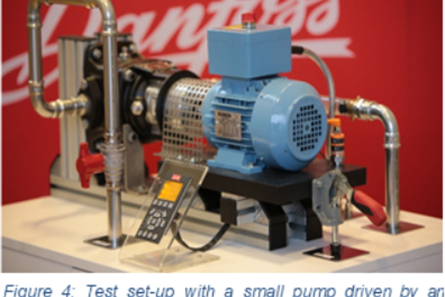
Figure 4 shows the test set-up with an induction motor driving a small pump. An angular misalignment can be created through slightly lifting the baseplate with the red handle. A vibration sensor has been installed on the baseplate of the motor to illustrate the concept. The analogue 4-20 mA sensor signal has been connected to the analogue input of the drive.
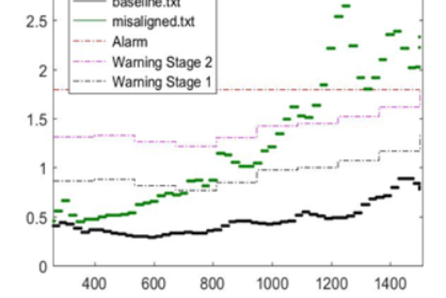
Figure 5 shows an example of test results. The measured vibration in mm/s versus the motor speed in RMS is shown for two scenarios. In the first scenario the system is in its healthy state. In this state, a baseline measurement is executed. The warning and alarm thresholds are derived based on the measured baseline. For the faulty scenario, a shaft misalignment is created by slightly lifting the motor baseplate through the red handle, see Figure 5. The measured vibration in faulty condition is shown in green.
In the above example, the drive can clearly detect this fault. For other applications, the baseline data can be very different. Typically, even in healthy state the vibration is dependent on speed. There can even by resonance points that need to be considered while monitoring. Other types of faults, e.g. unbalances, looseness, create different patterns.