In this document, we will focus exclusively on expansion valves for CO2 and how these solutions differ from other refrigerants.
This Application Guide provides guidelines for selection of the expansion valves best suited for CO2 systems. Some principles are relevant for CO2 only, while some principles apply to other refrigerants as well.
CO2 compared to other refrigerants
CO2 is different from other refrigerants. For instance, the pressure levels of CO2 solutions are much higher than for conventional refrigerants, and the viscosity and other properties also differ. All the different properties need to be taken into account when selecting expansion valves for CO2. In the Danfoss selection software, Coolselector®, all relevant parameters are taken into account to help you select the optimum valves.
When using the selection tool it is very important to understand the differences between a CO2 system and a conventional refrigeration system.
One thing that characterizes CO2 systems is that the liquid line is cold. Sometimes down to -10 °C, but often around 0°C. On conventional systems the liquid lines are typically at condensing pressure that is higher than ambient temperature. This means that the CO2 system has a heat input to the liquid line where other refrigerants will have a heat loss. The heat loss in conventional systems will show as additional sub cooling, whereas it will show as flash gas in a CO2 system. The flash gas will reduce the capacity of the expansion valve. However, the high pressure of the CO2 system results in high-density gas and therefore a reduced capacity drop compared to other refrigerants.
Example:
The ambient temperature is 32°C, the liquid temperature of the CO2 system is 2°C (saturated, no sub cooling), liquid line dimension is 7/8” and 100 meters long insulated with 20 mm insulation (λ=0,033W/mK), pressure drop is 1°K and cooling capacity is 100 kW (1500 kg/hr mass flow).
Heat input to the liquid can be obtained by using the formula below:
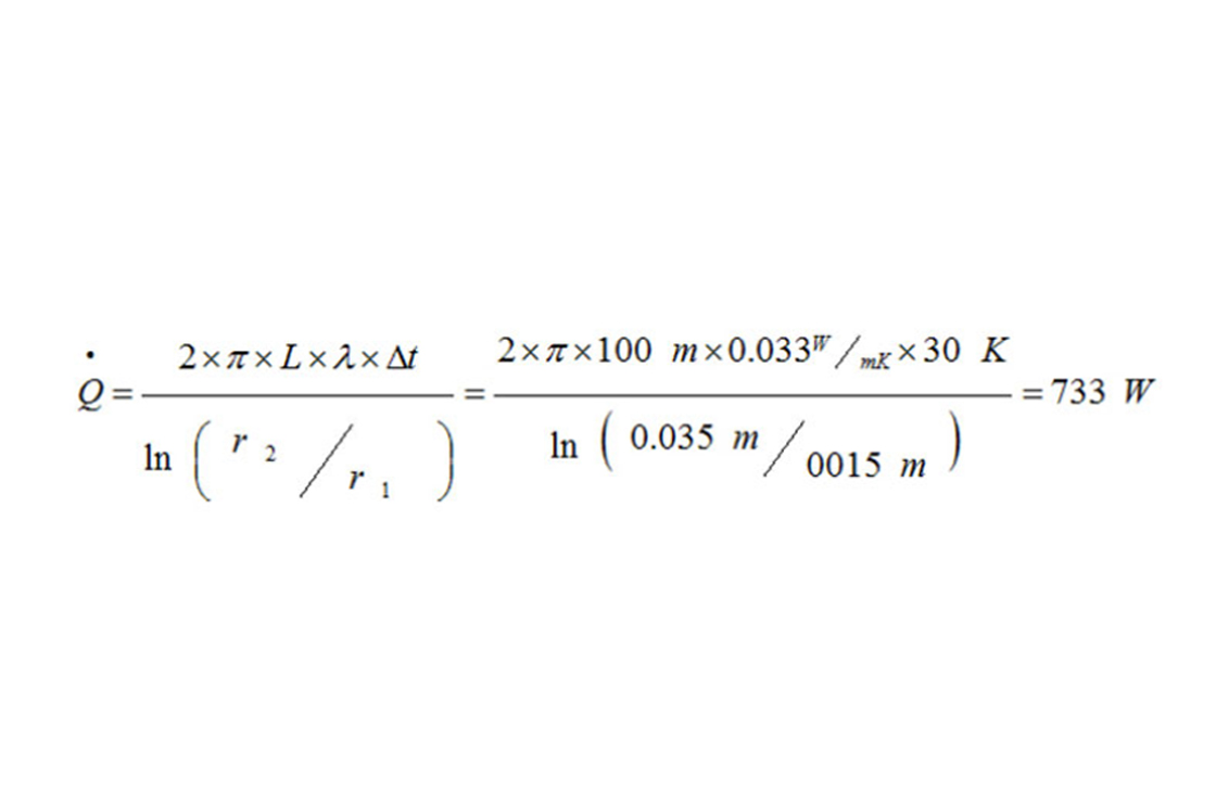
The pressure drop and the heat input will result in a gas fraction of approx. 2% on mass basis, but since the gas is 9 times lighter than the liquid, the fraction on volume basis is approximately 18%. In part load the heat input will remain approximately the same, but the mass flow will be reduced resulting in even larger gas fractions. Listening to CO2 valves the presence of gas in the flow can easily be heard.
One way to overcome the problem is to install sub-coolers, which is often an expensive solution. The solution normally applied is to oversize the valve to cope with the flash gas. As a rule of thumb a safety factor of 30% will provide sufficient safety margin for the valves to operate without problems both in low and high load conditions.
How to select the correct valve?
Step 1:
The tool recommended for valve selection is Coolselector®2. Here is a short guideline to the valve selection with the Coolselector®2 tool:
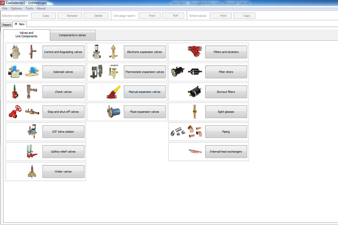
Figure 1: Select "Electronic expansion valves" on the component overview.
Step 2:
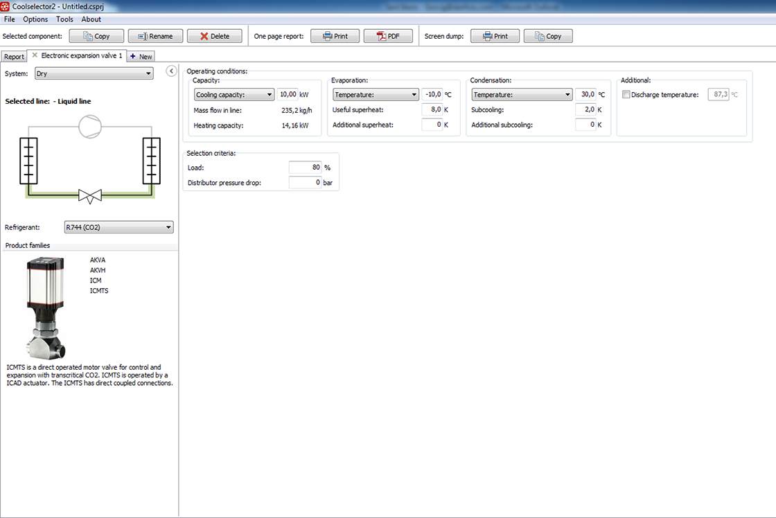
Figure 2: 1. Select "dry" on the "System" dropdown menu on the left and 2. Select the correct refrigerant, in this case R744 (CO2).
Step 3:
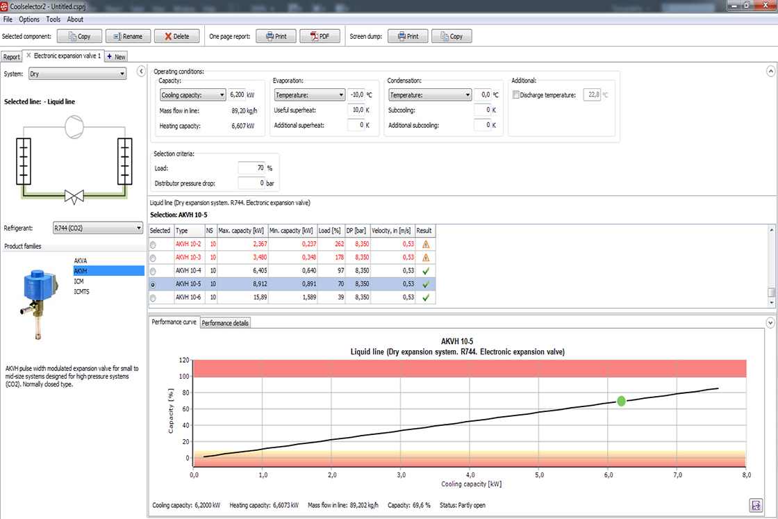
Figure 3:
- Select "AKVH" on the left, under "Product Families".
- Select the refrigerant "R744 (CO2)". As condensing pressure, the pressure in the receiver is used.
- Remember that in CO2 systems the sub cooling is normally 0 K.
- To get the safety factor, fill the load with 70%.
- In the output box the program selects AKVH 10-5. 70% utilization is used as a rule of thumb for correct dimensioning of the valve, but in some applications it might be too small.